Rank: Member
Groups: Member
Joined: 2/1/2012(UTC)
Posts: 332
Location: The Netherlands
Thanks: 4 times
Was thanked: 18 time(s) in 18 post(s)
|
|
|
|
|
|
|
|
Rank: Member
Groups: Member
Joined: 8/17/2010(UTC)
Posts: 368
Location: australia
Thanks: 8 times
Was thanked: 3 time(s) in 3 post(s)
|
Originally Posted by: Corpius  My pleasure. I dont seem to have a lot of luck asking questions on your site I was wondering, with the signal board you have 2x DC+ on each DC In & Out, why is that?
|
|
|
|
|
|
Rank: Member
Groups: Member
Joined: 2/1/2012(UTC)
Posts: 332
Location: The Netherlands
Thanks: 4 times
Was thanked: 18 time(s) in 18 post(s)
|
DC power out is used to drive the relay, but it can also be used for other applications if one wants or needs that. That why the relay and AC power connections board is more or less a separate board. The main reason the board can be separated is to keep the AC lines away from the signal lines. Please do contact me on my email address ( info at ce-designs dot net) for such questions. . Edited by user Monday, April 8, 2013 9:32:34 AM(UTC)
| Reason: Not specified Corpius attached the following image(s):  signal detection.JPG (36kb) downloaded 38 time(s).You cannot view/download attachments. Try to login or register. |
|
|
|
|
|
|
Rank: Member
Groups: Member
Joined: 8/17/2010(UTC)
Posts: 368
Location: australia
Thanks: 8 times
Was thanked: 3 time(s) in 3 post(s)
|
|
|
|
|
|
|
Rank: Member
Groups: Member
Joined: 2/1/2012(UTC)
Posts: 332
Location: The Netherlands
Thanks: 4 times
Was thanked: 18 time(s) in 18 post(s)
|
Nice and sleek design. Was it a kit or your own design? |
|
|
|
|
|
|
Rank: Member
Groups: Member
Joined: 8/17/2010(UTC)
Posts: 368
Location: australia
Thanks: 8 times
Was thanked: 3 time(s) in 3 post(s)
|
|
|
|
|
|
|
Rank: Member
Groups: Member
Joined: 8/17/2010(UTC)
Posts: 368
Location: australia
Thanks: 8 times
Was thanked: 3 time(s) in 3 post(s)
|
I have been having issues with the DAC turning itself on and off, it has a life of it's own. I thought it may not be a bad idea to smooth the supply coming from the SMPS that runs the MEGA. The supply is a XP Power SMPS ECE10US12
The SMPS manufactures says the maximum capacitance the SMPS should see is 550uF. I am not sure what would be the best configuration to smooth the supply (no need to get carried away :)) I have done some reading but am still lost in the woods.
Can anyome recommend a simple setup, if I used a CRC & say had 250uF for each C what should the R be? bearing in mind the supply is 12v & has limited current & I cannot afford to loose too much of either.
I would attach the SMPS data sheet but couldn't work out how to do it.
|
|
|
|
|
|
Rank: Member
Groups: Member
Joined: 2/1/2012(UTC)
Posts: 332
Location: The Netherlands
Thanks: 4 times
Was thanked: 18 time(s) in 18 post(s)
|
Why not use a simple linear 5V power supply that makes use of a 7808 voltage regulator? They are cheap and reliable. You could could also use a LM317 instead. That would even allow you to adjust the voltage. . Edited by user Friday, April 19, 2013 5:22:01 PM(UTC)
| Reason: Not specified |
|
|
|
|
|
|
Rank: Member
Groups: Member
Joined: 8/17/2010(UTC)
Posts: 368
Location: australia
Thanks: 8 times
Was thanked: 3 time(s) in 3 post(s)
|
Originally Posted by: Corpius  Why not use a simple linear 5V power supply that makes use of a 7808 voltage regulator? They are cheap and reliable. You could could also use a LM317 instead. That would even allow you to adjust the voltage.
. The SMPS is already installed, it takes up very little room, once the isolators are installed it will be isolated from the BIII, it will be on 24/7 & uses very little power on standby. I really cant see a reason not to use it :) The SMPS is probably not causing the issue, I just thought smoothing the supply wouldn't hurt, if only I knew somebody who could explain the formula to me, all I need is a capacitor, resistor & small inductor, should have paid more attention at school, nobody told me this stuff would become useful later in life :) 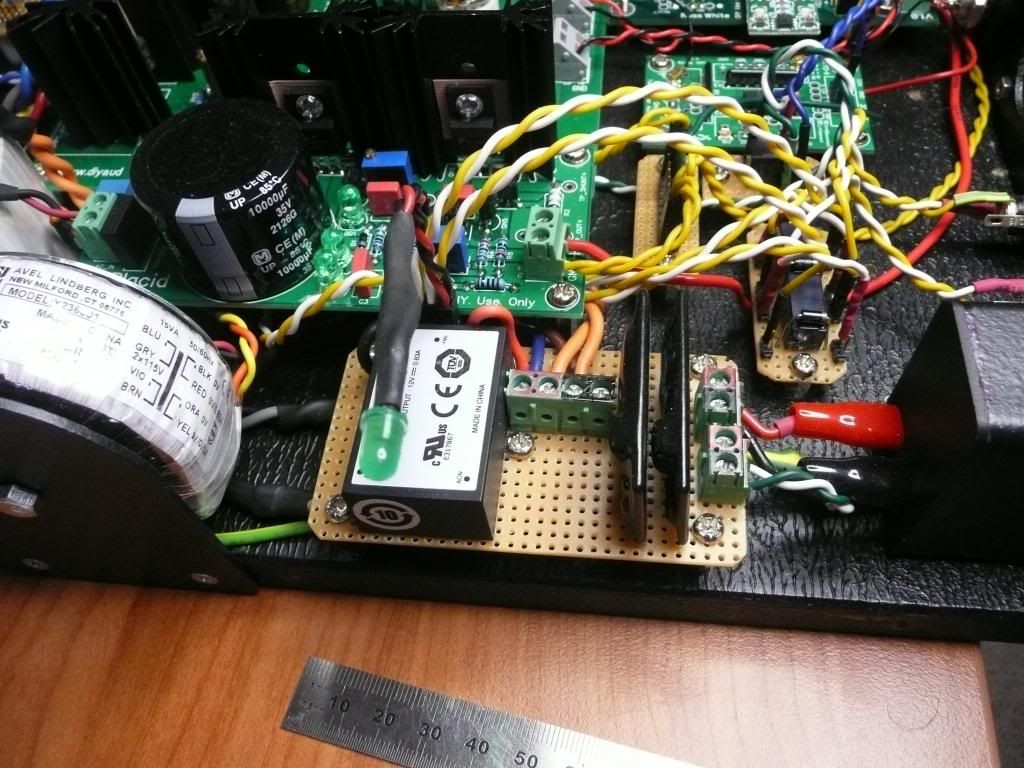 Edited by user Saturday, April 20, 2013 2:50:23 AM(UTC)
| Reason: Not specified
|
|
|
|
|
|
Rank: Member
Groups: Member
Joined: 8/17/2010(UTC)
Posts: 368
Location: australia
Thanks: 8 times
Was thanked: 3 time(s) in 3 post(s)
|
Finally got the rebuild started. 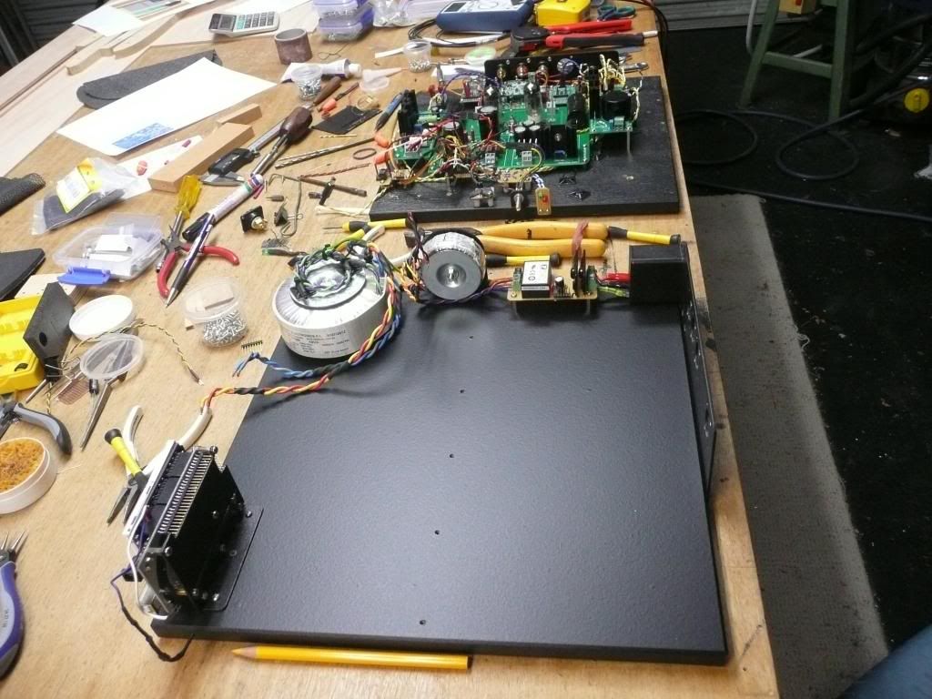
|
|
|
|
|
|
Rank: Member
Groups: Member
Joined: 8/17/2010(UTC)
Posts: 368
Location: australia
Thanks: 8 times
Was thanked: 3 time(s) in 3 post(s)
|
Finally I have managed to get the DAC inverted so the screen is the right way up. I took the opportunity to tidy up the layout a little bit, do a few mods & try and improve the wiring. Everything seems to be working EXCEPT, why is there always an EXCEPT  , It's not a biggy really just annoying. The lock LED it's working, not even a flicker, but I seem to be getting a good solid lock as I am getting good solid music. I made the overall board a bit bigger which meant I had to change the wires that ran to the LOCK & MUTE LED's. I had all sorts of problems getting the solder out of the BIII LED connections & am wondering if I have cooked a trace, what's the likely hood of that happening, anyone know? There's no voltage at the BIII LOCK LED output when the music is playing, The Mute light still works. 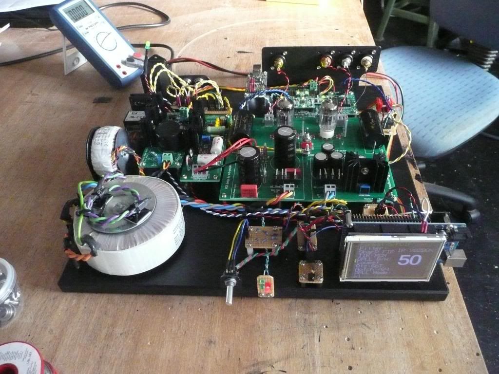 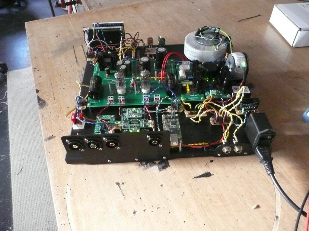 Edited by user Sunday, April 28, 2013 6:54:34 AM(UTC)
| Reason: Not specified
|
|
|
|
|
|
Rank: Member
Groups: Member
Joined: 8/17/2010(UTC)
Posts: 368
Location: australia
Thanks: 8 times
Was thanked: 3 time(s) in 3 post(s)
|
If I have cooked the LOCK LED trace, is there another way to get at the LOCK signal?
|
|
|
|
|
|
Rank: Administration
Groups: Administration, Customer
Joined: 10/24/2006(UTC)
Posts: 3,979
Location: Nashville, TN
Thanks: 25 times
Was thanked: 89 time(s) in 83 post(s)
|
Is it possible the LED is just backward? Or is possible it is also just needs to be replaced.
|
|
|
|
|
|
Rank: Administration
Groups: Administration, Customer
Joined: 10/24/2006(UTC)
Posts: 3,979
Location: Nashville, TN
Thanks: 25 times
Was thanked: 89 time(s) in 83 post(s)
|
BTW - You did a great job on those speakers. :)
|
|
|
|
|
|
Rank: Member
Groups: Member
Joined: 8/17/2010(UTC)
Posts: 368
Location: australia
Thanks: 8 times
Was thanked: 3 time(s) in 3 post(s)
|
Originally Posted by: Russ White  Is it possible the LED is just backward? Or is possible it is also just needs to be replaced. I checked the continuity, LED polarity and then I checked if there was voltage at the LOCK LED output on the board, there is no voltage at the LOCK LED output from the board when I have music playing. I then turned the music off and the MUTE LED came on and there was approx 1.9v at the MUTE LED output on the board.
|
|
|
|
|
|
Rank: Administration
Groups: Administration, Customer
Joined: 10/24/2006(UTC)
Posts: 3,979
Location: Nashville, TN
Thanks: 25 times
Was thanked: 89 time(s) in 83 post(s)
|
If the LED has gone bad as a short you would get no voltage.
|
|
|
|
|
|
Rank: Member
Groups: Member
Joined: 8/17/2010(UTC)
Posts: 368
Location: australia
Thanks: 8 times
Was thanked: 3 time(s) in 3 post(s)
|
Originally Posted by: Russ White  BTW - You did a great job on those speakers. :) Thanks, my own speakers are a bit different, not to everybody's taste, although they ended up looking better than I expected. I'll post a picture later, for those who may be interested. Edited by user Monday, April 29, 2013 1:45:37 AM(UTC)
| Reason: Not specified
|
|
|
|
|
|
Rank: Member
Groups: Member
Joined: 8/17/2010(UTC)
Posts: 368
Location: australia
Thanks: 8 times
Was thanked: 3 time(s) in 3 post(s)
|
I replaced the LED but no go I'm afraid. Still got music just no flashy light :( And there is another issue  As will see in the photo I have 2 SPDIF inputs going to the OTTO, lets say Input 1 & Input 2. When I plug my Squeezebox to Input 1, I get music, then I switch between the inputs I get music out of both (but one switch position has a better lock the other drops out), ok maybe the switching isn't working, here's the rub, then I plug my Squeezebox into Input 2 I still get music, which shouldn't be happening if the switch is not working!!. Any ideas what might be causing this issue I haven't tried connecting another source & play both at once to see what happens. 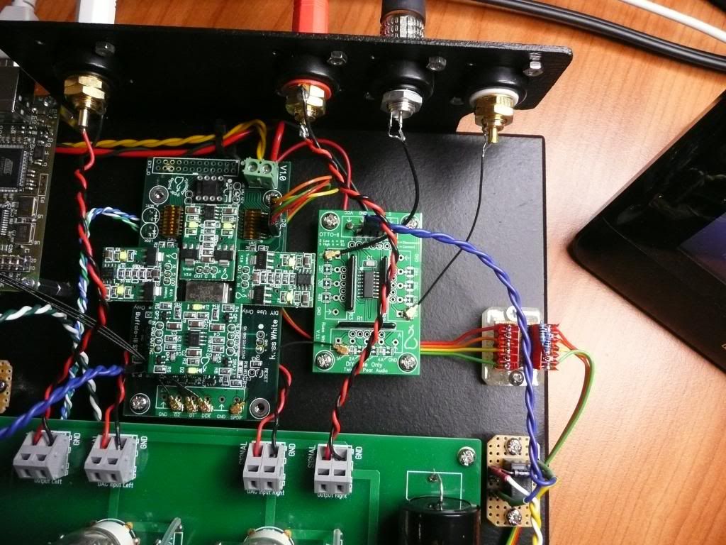 Edited by user Monday, April 29, 2013 10:51:29 AM(UTC)
| Reason: Not specified
|
|
|
|
|
|
Rank: Member
Groups: Member
Joined: 8/17/2010(UTC)
Posts: 368
Location: australia
Thanks: 8 times
Was thanked: 3 time(s) in 3 post(s)
|
I hope I'm not boring you with the photo's, one of the things I always wonder when I'm on this site is, all of these DIY guy's have built these great DAC's I wonder what speakers they use with their DAC's, I love looking at other peoples DIY projects. 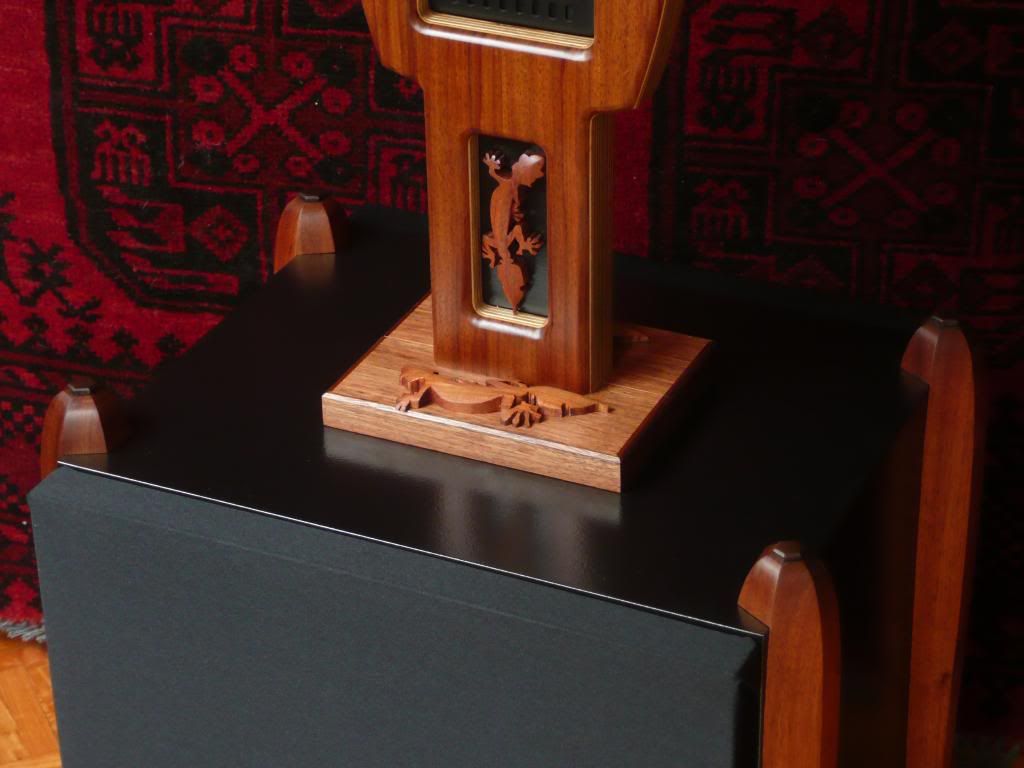 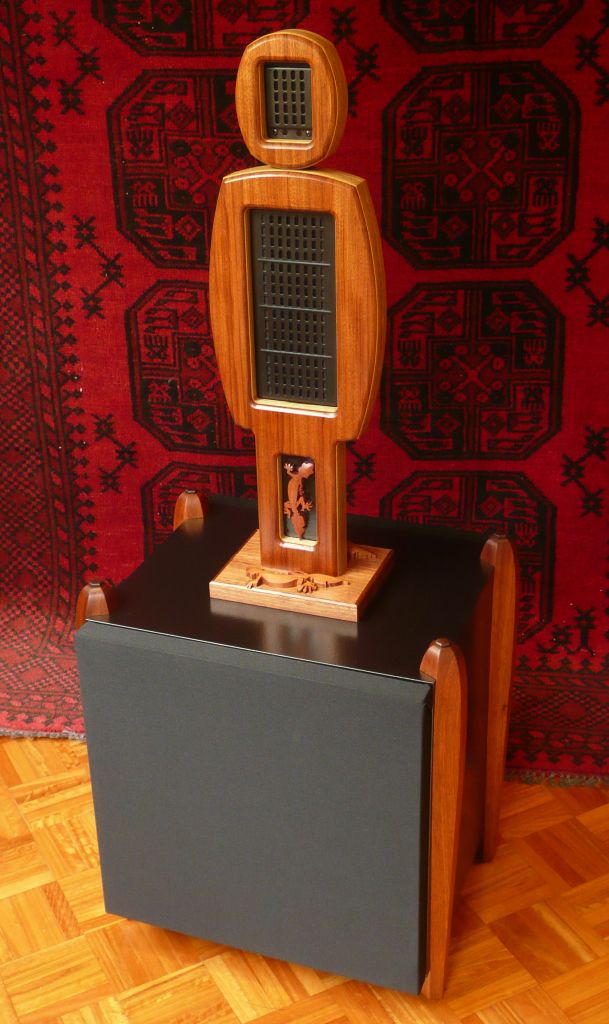
|
|
|
|
|
|
Rank: Administration
Groups: Administration, Customer
Joined: 10/24/2006(UTC)
Posts: 3,979
Location: Nashville, TN
Thanks: 25 times
Was thanked: 89 time(s) in 83 post(s)
|
It sounds like the Lock LED is not being driven.
A couple of possibilities:
1) Dead lock output (not very likely) at the DAC.
2) Maybe a bad solder joint at the lock pin at the DAC? Carefully touch this with a good soldering iron should clear that up.
3) Maybe a bad solder joint at the resistor between the output and the LED.
I don't think your source problem lies at the switch - since when you swapped inputs the problem stays with one source. I would just open up the DPLL a bit.
Cheers!
Russ
|
|
|
|
|
|
Forum Jump
You cannot post new topics in this forum.
You cannot reply to topics in this forum.
You cannot delete your posts in this forum.
You cannot edit your posts in this forum.
You cannot create polls in this forum.
You cannot vote in polls in this forum.