Rank: Member
Groups: Member
Joined: 8/17/2010(UTC)
Posts: 368
Location: australia
Thanks: 8 times
Was thanked: 3 time(s) in 3 post(s)
|
Originally Posted by: Russ White  It sounds like the Lock LED is not being driven.
A couple of possibilities:
1) Dead lock output (not very likely) at the DAC.
2) Maybe a bad solder joint at the lock pin at the DAC? Carefully touch this with a good soldering iron should clear that up.
3) Maybe a bad solder joint at the resistor between the output and the LED.
I don't think your source problem lies at the switch - since when you swapped inputs the problem stays with one source. I would just open up the DPLL a bit.
Cheers!
Russ "Maybe a bad solder joint at the resistor between the output and the LED."What resistor!! I assumed the resistor was built into the DAC as the LED's are often soldered directly to the board?
|
|
|
|
|
|
Rank: Administration
Groups: Administration, Customer
Joined: 10/24/2006(UTC)
Posts: 3,979
Location: Nashville, TN
Thanks: 25 times
Was thanked: 89 time(s) in 83 post(s)
|
R5 - just saying worth taking a look at it :)
|
|
|
|
|
|
Rank: Member
Groups: Member
Joined: 1/6/2012(UTC)
Posts: 305
Location: Plainfield, IL
Thanks: 11 times
Was thanked: 26 time(s) in 21 post(s)
|
Originally Posted by: DQ828 I hope I'm not boring you with the photo's, one of the things I always wonder when I'm on this site is, all of these DIY guy's have built these great DAC's I wonder what speakers they use with their DAC's, I love looking at other peoples DIY projects.
Good to see you got the display sorted out. Nice job on the speakers! I’m into hybrid ESL’s and bought used instead of DIY. I did build a heavy plinth for my Lenco idler drive turntable. Finish is automotive clearcoat. 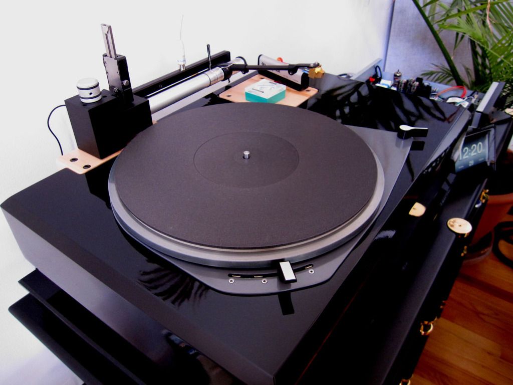 More pics here. http://s417.photobucket....524210053716115043427826My speakers/room. http://www.polkaudio.com...showcase/218_108_big.jpg |
|
|
|
|
|
|
Rank: Member
Groups: Member
Joined: 8/17/2010(UTC)
Posts: 368
Location: australia
Thanks: 8 times
Was thanked: 3 time(s) in 3 post(s)
|
Originally Posted by: SCompRacer Originally Posted by: DQ828 I hope I'm not boring you with the photo's, one of the things I always wonder when I'm on this site is, all of these DIY guy's have built these great DAC's I wonder what speakers they use with their DAC's, I love looking at other peoples DIY projects.
Good to see you got the display sorted out. Nice job on the speakers! I’m into hybrid ESL’s and bought used instead of DIY. I did build a heavy plinth for my Lenco idler drive turntable. Finish is automotive clearcoat. More pics here. http://s417.photobucket....524210053716115043427826My speakers/room. http://www.polkaudio.com...showcase/218_108_big.jpg Excellent stuff, I have been thinking of building a turntable, tell me about the cartridge arm & what's with the air hose in the wall? How's the bass in the ESL's? Are they reconditioned? Iv'e heard some good things about them. David
|
|
|
|
|
|
Rank: Member
Groups: Member
Joined: 8/17/2010(UTC)
Posts: 368
Location: australia
Thanks: 8 times
Was thanked: 3 time(s) in 3 post(s)
|
Originally Posted by: Russ White It sounds like the Lock LED is not being driven.
A couple of possibilities:
1) Dead lock output (not very likely) at the DAC.
2) Maybe a bad solder joint at the lock pin at the DAC? Carefully touch this with a good soldering iron should clear that up.
3) Maybe a bad solder joint at the resistor between the output and the LED.
I don't think your source problem lies at the switch - since when you swapped inputs the problem stays with one source. I would just open up the DPLL a bit.
Cheers!
Russ I'm now as sure as I can be that I cooked a trace, there was no continuity between R5 & the LED output, I tried reheating it with the iron & a dab of solder. Also if you followed the trace from the resistor it got to a couple of mm to the output & vanished, where with R2 I can see the trace right to the output. I have soldered a link as you will see in the photo & the LED now works, BTW the grey wire doesn't go anywhere I was just using it to hold the link while I soldered. I'm not sure I understand how I can get music from Inputs 1 (1B1) & 2 (1B2) via the OTTO even though I haven't changed the input selector, somehow the music signal is present at OTTO output 1A, when the music signal is sent to either 1B1 & 1B2, without me switching the input's. How do I open up the DPLL a bit? 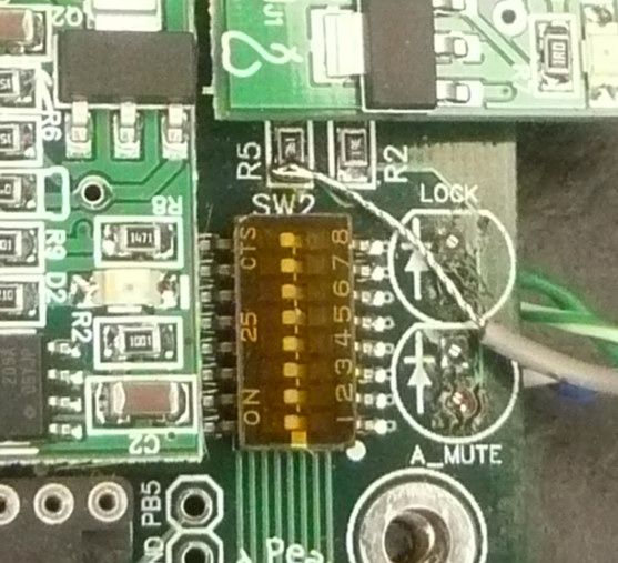 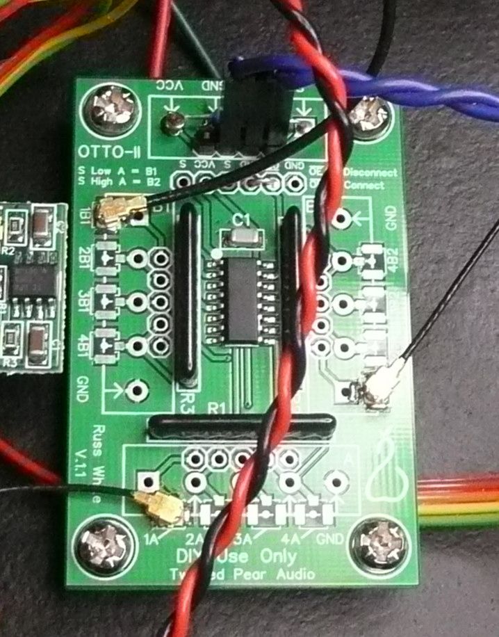
|
|
|
|
|
|
Rank: Administration
Groups: Administration, Customer
Joined: 10/24/2006(UTC)
Posts: 3,979
Location: Nashville, TN
Thanks: 25 times
Was thanked: 89 time(s) in 83 post(s)
|
Probably because you don't have a pull-down or a pull-up resistor installed at "S" on the OTTO. This leads to unpredictable behavior.
|
|
|
|
|
|
Rank: Administration
Groups: Administration, Customer
Joined: 10/24/2006(UTC)
Posts: 3,979
Location: Nashville, TN
Thanks: 25 times
Was thanked: 89 time(s) in 83 post(s)
|
Are you using a simple single pole switch? If so just install a ~10K pullup resistor between the VCC and S pads and you will be fine.
|
|
|
|
|
|
Rank: Member
Groups: Member
Joined: 1/6/2012(UTC)
Posts: 305
Location: Plainfield, IL
Thanks: 11 times
Was thanked: 26 time(s) in 21 post(s)
|
Originally Posted by: Russ White Probably because you don't have a pull-down or a pull-up resistor installed at "S" on the OTTO. This leads to unpredictable behavior. +1 on that. I'm on record here somewhere having issues with no pull up/down resistors in the OTTO II. Switching was not immediate or it hung or stuck on one channel despite being switched back to the other. No issues at all using a pull up or down resistor. |
|
|
|
|
|
|
Rank: Administration
Groups: Administration, Customer
Joined: 10/24/2006(UTC)
Posts: 3,979
Location: Nashville, TN
Thanks: 25 times
Was thanked: 89 time(s) in 83 post(s)
|
Only use a pull down resistor if you plan on driving S high with a controller or switch who's VCC is no higher than the OTTO-II VCC. If you are using a simple switch to GND or an open-drain controller output to pull S low then the pull-up resistor is the right choice. :) Edited by user Tuesday, April 30, 2013 4:38:18 PM(UTC)
| Reason: Not specified
|
|
|
|
|
|
Rank: Member
Groups: Member
Joined: 1/6/2012(UTC)
Posts: 305
Location: Plainfield, IL
Thanks: 11 times
Was thanked: 26 time(s) in 21 post(s)
|
Originally Posted by: DQ828
Excellent stuff, I have been thinking of building a turntable, tell me about the cartridge arm & what's with the air hose in the wall?
How's the bass in the ESL's? Are they reconditioned? Iv'e heard some good things about them.
David
Thanks for the kind words. The arm is an Advanced Analog MG-1. It is crude compared to the high priced Rockport’s and ET air arms, but effective at its job and reasonably priced ($599 new less air compressor, $280 for the Ultra arm). I bought it used with standard and Ultra arms which was even better deal. The noisy air compressor is mounted in the basement. The air line goes through the wall. I used a push-lock bulkhead fitting for a nice professional look and ease of disconnect. That fitting is mounted in a Cat5/phone jack wall plate. Not pictured is a combination air filter / expansion tank by my audio rack. An expansion tank smoothes the air pump pulses so the tonearm gets steady stream air pressure. The cartridge is a Dynavector Karat 17D3. I also have a Denon 103R that I removed the plastic body from and installed an aluminum body. The Lenco is an excellent Swiss design but was placed in a cheap hollow plinth. A fellow named Jean Nantais started applying the same formula to the Lenco as the audiophile priced Garrard’s. Heavy plinths to absorb vibes from the high torque motor. Done right there isn’t an arm or cartridge you couldn’t mount on them. They drive through the most difficult grooves without slowing at all. Speakers are Innersound MK III with the Ultrastat panels. Instead of powder coated stators, a high value dielectric material is cast over the stator grids. A CNC machine mills slots between the wire grids making them arc proof. Often times powder coating does hot adhere to sharp edges of the metal stators which could result in arcing. (Been there with metal stator ESL’s. Break the epoxy out and carefully apply to the bare areas without getting any on the ESL diaphragm). Roger Sanders also came up with an embedded coating that does not wear off like some ESL panels. Result is no worries about insects, pet fur or humidity. Hybrid design means a custom long excursion 10" SEAS woofer resides in an 8 foot long folded transmission line bass module. A 600WPC @ 4 Ohm active crossover bass amp powers the woofer. A 720 WPC @ 4 Ohms Sanders amp powers the panels. Bass has slam and is sharp and articulate. They integrate very well with the panels. Bass and mid bass are adjustable on the active xover via front panel controls or remote control. These will play extremely loud if desired and sound great doing it. |
|
|
|
|
|
|
Rank: Member
Groups: Member
Joined: 1/6/2012(UTC)
Posts: 305
Location: Plainfield, IL
Thanks: 11 times
Was thanked: 26 time(s) in 21 post(s)
|
Originally Posted by: Russ White Only use a pull down resistor if you plan on driving S high with a controller or switch who's VCC is no higher than the OTTO-II VCC. If you are using a simple switch to GND or an open-drain controller output to pull S low then the pull-up resistor is the right choice. :) Thanks. I just can't remember all this important stuff. I just recall the issues without using a resistor. Edited by user Tuesday, April 30, 2013 5:50:41 PM(UTC)
| Reason: Not specified |
|
|
|
|
|
|
Rank: Administration
Groups: Administration, Customer
Joined: 10/24/2006(UTC)
Posts: 3,979
Location: Nashville, TN
Thanks: 25 times
Was thanked: 89 time(s) in 83 post(s)
|
Oh your definitely right. It will not work correctly unless 'S' is solidly pulled in one way or the other. :)
|
|
|
|
|
|
Rank: Member
Groups: Member
Joined: 8/17/2010(UTC)
Posts: 368
Location: australia
Thanks: 8 times
Was thanked: 3 time(s) in 3 post(s)
|
Originally Posted by: Russ White Are you using a simple single pole switch? If so just install a ~10K pullup resistor between the VCC and S pads and you will be fine. If you look really closely you can see (maybe) there is a resistor hidden behind the socket. It is a 10k resistor which connects VCC to S. To make life easier I have loaded another photo. I am doing the switching with a simple switch, in my case a relay driven by the Arduino. I did remove the ground wire on the Otto to extend it to the new star ground location so maybe I have damaged the Otto as well, I'll have a closer look on the weekend. When I first put the DAC back together everything seemed to work except the LOCK LED, Now I'm plagued with issues again mainly to do with the Arduino. I'm going to put an isolator on the I2C lines on the weekend & I'm hoping that having the DAC & the Arduino separated electrically will solve my issues. I'm fast running out of ideas. 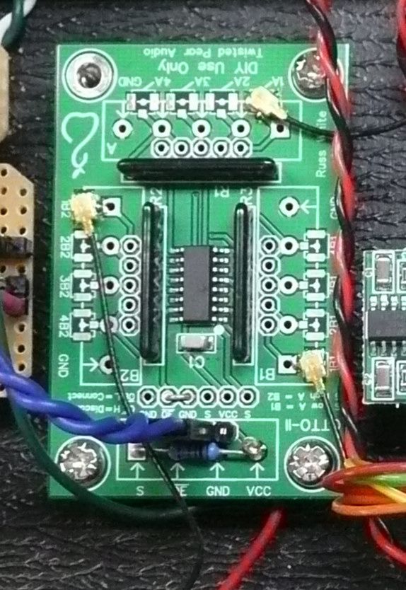 Edited by user Wednesday, May 1, 2013 9:50:06 AM(UTC)
| Reason: Not specified
|
|
|
|
|
|
Rank: Member
Groups: Member
Joined: 8/17/2010(UTC)
Posts: 368
Location: australia
Thanks: 8 times
Was thanked: 3 time(s) in 3 post(s)
|
If I cant get the DAC to work reliably with my Arduino setup I'm may put the firmware chip back in & use the approach of my first DAC which was to have everything external.
With my DAC 1 about the only outstanding problem I had was getting the 4 way SPDIF to work properly, I was going to try lowering the voltage to the SPDIF as discussed elsewhere. I was wondering if I could just put a diode in series with the + from the Placid HD and use the voltage drop across the diode to lower the voltage to the 4 way SPDIF?
|
|
|
|
|
|
Rank: Member
Groups: Member
Joined: 2/1/2012(UTC)
Posts: 332
Location: The Netherlands
Thanks: 4 times
Was thanked: 18 time(s) in 18 post(s)
|
You could use a resistor in series before the 4 way Spdif and calculate the value of the resistor to get the desired voltage. First apply Ohms law: V = I * R the voltage (V) applied is 5.25V Current (I) sourced by the 4 way spdif is around 30mA Than the resistance (R) of the way spdif = 5.25 / 0.03 = 175 OhmWhen adding a 10 ohm resistor in series, the voltage drop across this resistor is: Vi = Vt *(Ri / R1+R2) Vi = 5.25 * (10 / (10+175) = 0.28VSo the voltage that the 4 way spdif sees is 5.25 - 0.25 = 4.97 V U can use a voltage divider calculator like this one to help you with calculating the correct value: http://www.rapidtables.c...e_Divider_Calculator.htm |
|
|
|
|
|
|
Rank: Member
Groups: Member
Joined: 8/17/2010(UTC)
Posts: 368
Location: australia
Thanks: 8 times
Was thanked: 3 time(s) in 3 post(s)
|
Thanks, I'll put that in the notebook.
Tomorrow I'm going to try installing a I2C isolator between the BIII & the Mega to see if it helps with the issues I'm having. The I2C line is the only electrical connection between them, if that doesn't work I might try a different PSU for the mega.
|
|
|
|
|
|
Rank: Member
Groups: Member
Joined: 2/1/2012(UTC)
Posts: 332
Location: The Netherlands
Thanks: 4 times
Was thanked: 18 time(s) in 18 post(s)
|
Have you connected a ground line between the arduino and BIII? |
|
|
|
|
|
|
Rank: Member
Groups: Member
Joined: 8/17/2010(UTC)
Posts: 368
Location: australia
Thanks: 8 times
Was thanked: 3 time(s) in 3 post(s)
|
Originally Posted by: Corpius Have you connected a ground line between the arduino and BIII? There is a ground in the level converter setup that links the BIII & Arduino, but other than that I don't have one at the moment, I'm sure I have tried an extra ground between the BIII main ground point & the Arduino main ground point previously and it had no effect. Edited by user Friday, May 3, 2013 12:02:36 AM(UTC)
| Reason: Not specified
|
|
|
|
|
|
Rank: Member
Groups: Member
Joined: 8/17/2010(UTC)
Posts: 368
Location: australia
Thanks: 8 times
Was thanked: 3 time(s) in 3 post(s)
|
I couldn't get the isolator to work :( I have remove the Hardware Debounce, and replaced my new DYI IR board with the one from my other DAC and I seem (still need more testing) to be back to where I was before I inverted the screen, which should mean everything works except the DAC still turns itself on. 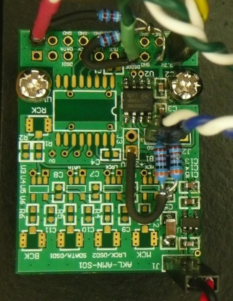
|
|
|
|
|
|
Rank: Member
Groups: Member
Joined: 2/1/2012(UTC)
Posts: 332
Location: The Netherlands
Thanks: 4 times
Was thanked: 18 time(s) in 18 post(s)
|
Which isolator are you using? Can't read it from the picture.
I'm using the ADuM1250. This works perfect. Are you powering side 2 of the isolator from the DAC? |
|
|
|
|
|
|
Forum Jump
You cannot post new topics in this forum.
You cannot reply to topics in this forum.
You cannot delete your posts in this forum.
You cannot edit your posts in this forum.
You cannot create polls in this forum.
You cannot vote in polls in this forum.

