Rank: Member
Groups: Member
Joined: 3/17/2013(UTC) Posts: 1  Location: Bergen
|
Originally Posted by: avr300  Jobs done to the BP as well.
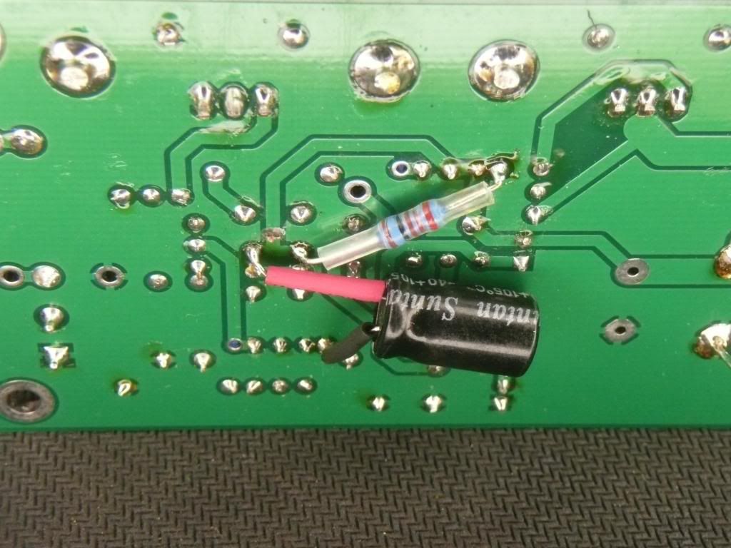
Flat line output now. This is a really important update. Does this apply to the Placid BP V. 2.1.2 as well? And if so, do you know where to cut the trace?
|
|
|
|
|
|
Rank: Member
Groups: Member
Joined: 6/17/2008(UTC) Posts: 921  Thanks: 1 times
Was thanked: 70 time(s) in 69 post(s)
|
Nope, only the HD version(s). edit: Because the non-HD versions is not affected by this. Edited by user Monday, April 15, 2013 7:08:02 PM(UTC)
| Reason: Not specified
|
|
|
|
|
|
Rank: Member
Groups: Member
Joined: 3/8/2011(UTC)
Posts: 136
Location: Norway
Was thanked: 2 time(s) in 2 post(s)
|
For us who don't want to cut the trace,,,,,,,we use a bigger trafo and a bigger Mundorf cap 22 or 33000uf on Placid HD.
Believe me, it works.
|
|
|
|
|
|
Rank: Administration
Groups: Administration, Customer
Joined: 10/24/2006(UTC)
Posts: 3,979
Location: Nashville, TN
Thanks: 25 times
Was thanked: 89 time(s) in 83 post(s)
|
|
|
|
|
|
|
Rank: Member
Groups: Member
Joined: 11/21/2008(UTC)
Posts: 314
Location: Norway
|
I use choke input supplies to feed rectified dc to Placid HDs 250va x-formers sounds terriffic! best Leif Edited by user Wednesday, April 17, 2013 9:41:04 AM(UTC)
| Reason: Not specified
|
|
|
|
|
|
Rank: Member
Groups: Member
Joined: 8/17/2010(UTC)
Posts: 368
Location: australia
Thanks: 8 times
Was thanked: 3 time(s) in 3 post(s)
|
So should all Placid HD owners be doing this?
I have had serious trouble with your site in the last couple of days & for that matter a lot of US sites I visit, even from my work computer same issue, really slow, dropping out etc.
|
|
|
|
|
|
Rank: Administration
Groups: Administration, Customer
Joined: 10/24/2006(UTC)
Posts: 3,979
Location: Nashville, TN
Thanks: 25 times
Was thanked: 89 time(s) in 83 post(s)
|
It's completely optional. But its a fun mod if you feel like doing it. :)
|
|
|
|
|
|
Rank: Member
Groups: Member
Joined: 6/17/2008(UTC) Posts: 921  Thanks: 1 times
Was thanked: 70 time(s) in 69 post(s)
|
Try it - and listen <big smile>
|
|
|
|
|
|
Rank: Advanced Member
Groups: Member
Joined: 11/3/2010(UTC)
Posts: 52
Location: Belgorod, Russia
Thanks: 6 times
Was thanked: 1 time(s) in 1 post(s)
|
Hi avr300!
Could you please summarize which changes you've made, apart from cutting the trace and adding resistor and cap to QP7/QP8 emitters?
Reason why I'm asking, is because I too saw Placid ripple on my old soviet oscilloscope. And after adding the cap and resistor to emitters and cutting the trace, the ripple was still there.
After reading through this topic again, I see that C2 and C3 should be changed to some higher value, correct?
Anything else maybe?
Thanks,
Fedor
|
|
|
|
|
|
Rank: Member
Groups: Member
Joined: 8/17/2010(UTC)
Posts: 368
Location: australia
Thanks: 8 times
Was thanked: 3 time(s) in 3 post(s)
|
Originally Posted by: fred_com  Hi avr300!
Reason why I'm asking, is because I too saw Placid ripple on my old soviet oscilloscope. And after adding the cap and resistor to emitters and cutting the trace, the ripple was still there.
Thanks,
Fedor
Don't tell me that, I just finished the mod :) Is this what we are suppose to do? I don't have a Scope to check it :( 
|
|
|
|
|
|
Rank: Advanced Member
Groups: Member
Joined: 11/3/2010(UTC)
Posts: 52
Location: Belgorod, Russia
Thanks: 6 times
Was thanked: 1 time(s) in 1 post(s)
|
Yes, that's exactly how I did it too (only difference is I connected negative cap side to the MOSFET ground).
I guess we need to wait for avr300 or Russ (if he's checking forum while on vacation) to clarify that :)
|
|
|
|
|
|
Rank: Member
Groups: Member
Joined: 6/17/2008(UTC) Posts: 921  Thanks: 1 times
Was thanked: 70 time(s) in 69 post(s)
|
Hi guys.. It looks very reasonable. You have to check for ripple across C2 and C3 (C3 @ BP version). I have increased both C2 and C3 to 470uF. Once C2 and C3 are clean, and you have done the decoupling of the supply to the error amplifier, things starts to sing ;-) (you really can't do this kind of mods without an oscilloscope, you have to be able to see what's going on) Edited by user Saturday, April 20, 2013 3:11:54 PM(UTC)
| Reason: Not specified
|
|
|
|
|
|
Rank: Advanced Member
Groups: Member
Joined: 11/3/2010(UTC)
Posts: 52
Location: Belgorod, Russia
Thanks: 6 times
Was thanked: 1 time(s) in 1 post(s)
|
Thanks for the answer, avr.
I took another look at the new schematic that Russ posted, and noticed that he used 100uF for C2 and C3. I had plenty of caps with this value, so I exchanged film C2 and C3 with those electrolytics (observing the polarity).
After that I've checked V_REF, checked output - the ripple is gone!
Thanks Russ and avr!
|
 1 user thanked fred_com for this useful post.
|
|
|
|
Rank: Administration
Groups: Administration, Customer
Joined: 10/24/2006(UTC)
Posts: 3,979
Location: Nashville, TN
Thanks: 25 times
Was thanked: 89 time(s) in 83 post(s)
|
No need to go that high. Even 22uf will significantly reduce the ripple. :)
|
|
|
|
|
|
Rank: Administration
Groups: Administration, Customer
Joined: 10/24/2006(UTC)
Posts: 3,979
Location: Nashville, TN
Thanks: 25 times
Was thanked: 89 time(s) in 83 post(s)
|
The reason you don't want to go too high is that it will take a while for the voltages to come up to where they should be., it also leave a large current discharge on power down. Still if you be ok to go higher, but I would not go more than about 100uf.
|
|
|
|
|
|
Rank: Administration
Groups: Administration, Customer
Joined: 10/24/2006(UTC)
Posts: 3,979
Location: Nashville, TN
Thanks: 25 times
Was thanked: 89 time(s) in 83 post(s)
|
The reason you don't want to go too high is that it will take a while for the voltages to come up to where they should be., it also leave a large current discharge on power down. Still if you be ok to go higher, but I would not go more than about 100uf.
|
 1 user thanked Russ White for this useful post.
|
|
|
|
Rank: Member
Groups: Member
Joined: 8/17/2010(UTC)
Posts: 368
Location: australia
Thanks: 8 times
Was thanked: 3 time(s) in 3 post(s)
|
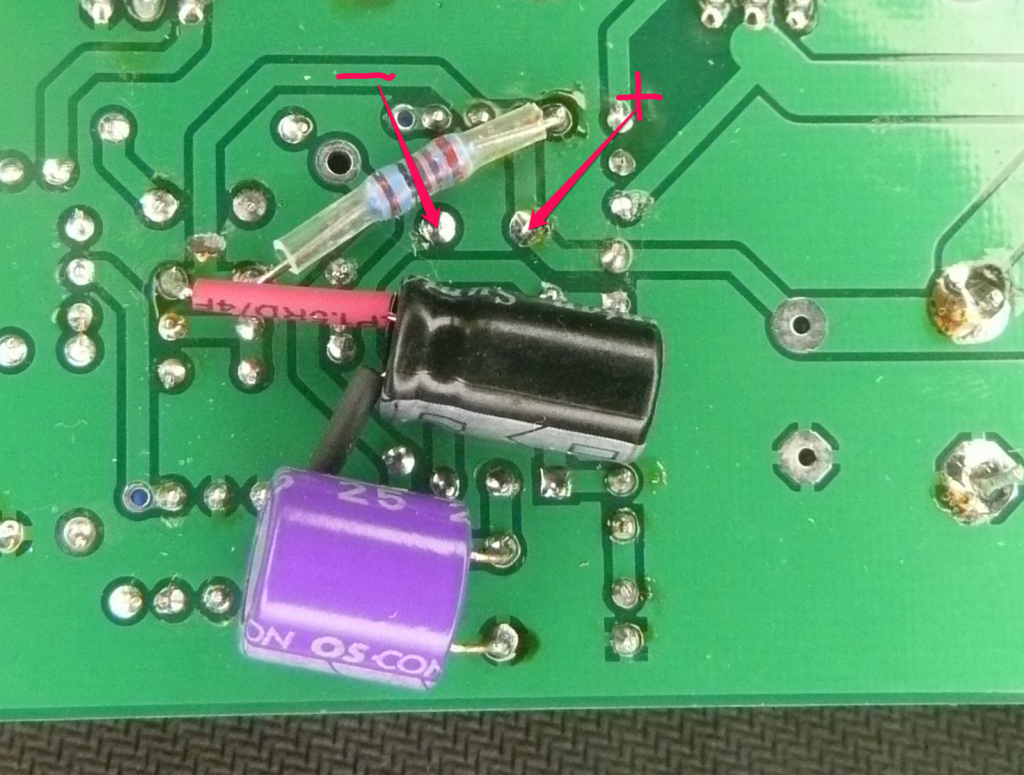
I had some 25V 33uF capacitors laying around to use for C2 & C3. I just wanted to check that I had the polarity correct for C2 before I install it, please see photo.  Is there anything else I should do to the Placid HD before I fire it up again? Edited by user Sunday, April 21, 2013 5:21:12 AM(UTC)
| Reason: Not specified
|
|
|
|
|
|
Rank: Member
Groups: Member
Joined: 6/17/2008(UTC) Posts: 921  Thanks: 1 times
Was thanked: 70 time(s) in 69 post(s)
|
That's correct.
And no, that should be it. Enjoy the music.
|
|
|
|
|
|
Rank: Member
Groups: Member
Joined: 4/9/2011(UTC)
Posts: 37
Location: Lisbon
Thanks: 1 times
|
Hi
I dont have a scope. Can the ripple problem be present with Placid HD, stock trannies and Buffalo 3 Standard build? Are there any diferent issues in avr300 setup to the present Buffalo 3 (non SE) build advice?
Regards
|
|
|
|
|
|
Rank: Advanced Member
Groups: Member
Joined: 11/3/2010(UTC)
Posts: 52
Location: Belgorod, Russia
Thanks: 6 times
Was thanked: 1 time(s) in 1 post(s)
|
Hi guys,
one note about this mod - when modding negative side of Placid HD BP polarities of electrolytic caps should be reversed (C2, C3 and the new one).
If polarity is not reversed - the negative side voltage will sag.
I don't know how this works, but I'm sure Russ will clarify this :)
Thanks,
Fedor
|
|
|
|
|
|
Forum Jump
You cannot post new topics in this forum.
You cannot reply to topics in this forum.
You cannot delete your posts in this forum.
You cannot edit your posts in this forum.
You cannot create polls in this forum.
You cannot vote in polls in this forum.