Rank: Advanced Member
Groups: Member
Joined: 11/3/2010(UTC)
Posts: 52
Location: Belgorod, Russia
Thanks: 6 times
Was thanked: 1 time(s) in 1 post(s)
|
|
|
|
|
|
|
Rank: Member
Groups: Member
Joined: 10/25/2012(UTC) Posts: 1 
|
Hi Russ
is a new PCB available?
Thank s
|
|
|
|
|
|
Rank: Administration
Groups: Administration, Customer
Joined: 10/24/2006(UTC)
Posts: 2,869
Location: Massachusetts, USA
Thanks: 2 times
Was thanked: 141 time(s) in 134 post(s)
|
Originally Posted by: Patrik1005  Hi Russ
is a new PCB available?
Thank s No. We have increased the sizes of the available power transformers for people try to power more demanding loads.
|
|
|
|
|
|
Rank: Member
Groups: Member
Joined: 4/20/2012(UTC)
Posts: 13
Location: Serbia, Nis
Thanks: 3 times
|
Hello, Russ I have exactly the same problem as avr300. Do you prefer first http://www.twistedpearaudio.com...at-output.aspx#post18992or the second solution to the ripple problem. http://www.twistedpearaudio.com...at-output.aspx#post19010Placid HD with ripple I have is about 6mVpp(low frequency) on 5.25V DC output, input ripple is about 400mV p-p and this one is for Buffalo III. Current used is about 520mA (about 60mA shunted). Trafo is PCB type HAHN 2x9V(but output is 2x11.7V) 2x15VA and I only using one trafo output for the Buffalo. The other is for a second Placid HD (5V DC) with much smaller current demand so it's not critical(maybe). In the DAC box I have 4 trafos: 1) 2x9V (2x15VA) for 2XPlacidHD - Buffalo and Acko reclocker board 2) 2x15V (50VA) for Placid HDBP - IVY board 3) 2x9V (2x15VA) for DIYINHK tps4700 dual power supply - remaining power supplies for Acko reclocker board 4) 2x9V (2x8VA) for arduino board and one free output (for now) This is a temporary box.  DAC box is earthed but I'm not sure should I connect power ground(s) to the same point(earth) and from which point because of many power supplies with grounds interconnected. Arduino controller has isolated ground from the Buffalo by TI iso1540. Display used is Noritake VFD CU20045SCPB-W5J. Regards.
|
|
|
|
|
|
Rank: Member
Groups: Member
Joined: 6/17/2008(UTC) Posts: 921  Thanks: 1 times
Was thanked: 70 time(s) in 69 post(s)
|
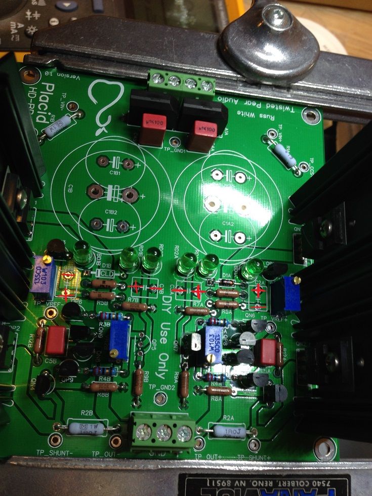
My point of view, the latter. I tried both. Together with a beefed up transformer (15V, 160VA) and upgraded main caps (from 10.000uF to 33.000uF) this is the best mod I ever have done to the analogue side! (after doing this, I actually boxed up the DAC, put the lid on, just playing now) Attached are the important parts. Have fun. Edited by user Tuesday, February 4, 2014 7:21:06 PM(UTC)
| Reason: spelling avr300 attached the following image(s):  cut.JPG (36kb) downloaded 93 time(s).You cannot view/download attachments. Try to login or register.
|
|
|
|
|
|
Rank: Administration
Groups: Administration, Customer
Joined: 10/24/2006(UTC)
Posts: 2,869
Location: Massachusetts, USA
Thanks: 2 times
Was thanked: 141 time(s) in 134 post(s)
|
I would start with just a larger trafo and see if it is enough. One half of a 15VA trafo for a Placid/Buffalo is too small.
|
|
|
|
|
|
Rank: Member
Groups: Member
Joined: 4/20/2012(UTC)
Posts: 13
Location: Serbia, Nis
Thanks: 3 times
|
It's kind a difficult to find these current regulation diodes 1n5314 here in Serbia and I have to order from Farnell. I will try to replace it with a jfet current source in the mean time, and double the main cap to 22000uF and parallel secondary output. Did some simulations in spice and for nominal part values and current consumption about 550mA I get exactly what I've measured by oscilloscope. Even if put zero secondary winding resistance I still get similar results. .... Trafo is 30VA total, but if DC current is about 550 mA on 11.5V input then power is 6.3 W. It should be enough, but not for low input ripple so I shall biff up main capacitor. Edited by user Wednesday, February 5, 2014 1:40:50 PM(UTC)
| Reason: Not specified
|
|
|
|
|
|
Rank: Member
Groups: Member
Joined: 6/17/2008(UTC) Posts: 921  Thanks: 1 times
Was thanked: 70 time(s) in 69 post(s)
|
Just substitute the CLD with a (calculated) resistor. Just be aware that the current going through the LED will change when you adjust the Vout. It's not a problem for me, I don't adjust the Vout - it just sits there @+-15V ( and 5V2) Don't rush upgrading the main caps. 10.000uF is more than enough. I just had the caps. Edited by user Wednesday, February 5, 2014 5:54:46 PM(UTC)
| Reason: Not specified
|
|
|
|
|
|
Rank: Member
Groups: Member
Joined: 3/8/2011(UTC)
Posts: 136
Location: Norway
Was thanked: 2 time(s) in 2 post(s)
|
Hi guys
Just wonder if you have plans for a new version of the Placid.
If so, aproximately how far in the future will it bee before it turns up ?
Or is the Placid good as it is when using bigger trafo's ? ( thinking on the ripple problem at output )
|
|
|
|
|
|
Rank: Member
Groups: Member
Joined: 8/27/2013(UTC)
Posts: 9
|
Hi,
will every placid HD have benefit from bigger trafo, or it is just those that are affected because of config parameters (Vout, shunt current, ...)
I'm trying to find out an oscilloscope to measure this, but would upgrade trafo's anyway.
Would go with next change from your site:
1 pcs 2x9V (15VA) -> 1 pcs 2x9V (30V) [secondariness in parallel] for Buffalo III
1 pcs 2x15V (30VA) -> 2pcs 2x15v(30VA) or 1pcs 2x15V(50va) [secondariness in parallel] for Legato
Is this only change that you are recommending for current Placid HD (BP) until new version is available?
Thanks in advance
|
|
|
|
|
|
Rank: Member
Groups: Member
Joined: 3/8/2011(UTC)
Posts: 136
Location: Norway
Was thanked: 2 time(s) in 2 post(s)
|
Russ @
Thank you for that info. I will order the new versions of both the HD and BP Placids as soon as they get available. Looking forward to another step to "heaven".
|
|
|
|
|
|
Rank: Member
Groups: Member
Joined: 4/20/2012(UTC)
Posts: 13
Location: Serbia, Nis
Thanks: 3 times
|
I've been busy lately so I only had time to try double the secondaries(no changes at all) and after that changed the main cap to 22000 which reduced the ripple on output down to about 2mVpp at least in lower frequency band. Now I see that Russ redesigned the placid's so we will have a chance to try out complete solution. Edited by user Wednesday, February 12, 2014 3:36:34 PM(UTC)
| Reason: Not specified
|
|
|
|
|
|
Rank: Member
Groups: Member
Joined: 8/22/2010(UTC) Posts: 38  Thanks: 14 times
|
Originally Posted by: avr300  Yes certainly, my pleasure.
Panasonic FM 470u, 16v.
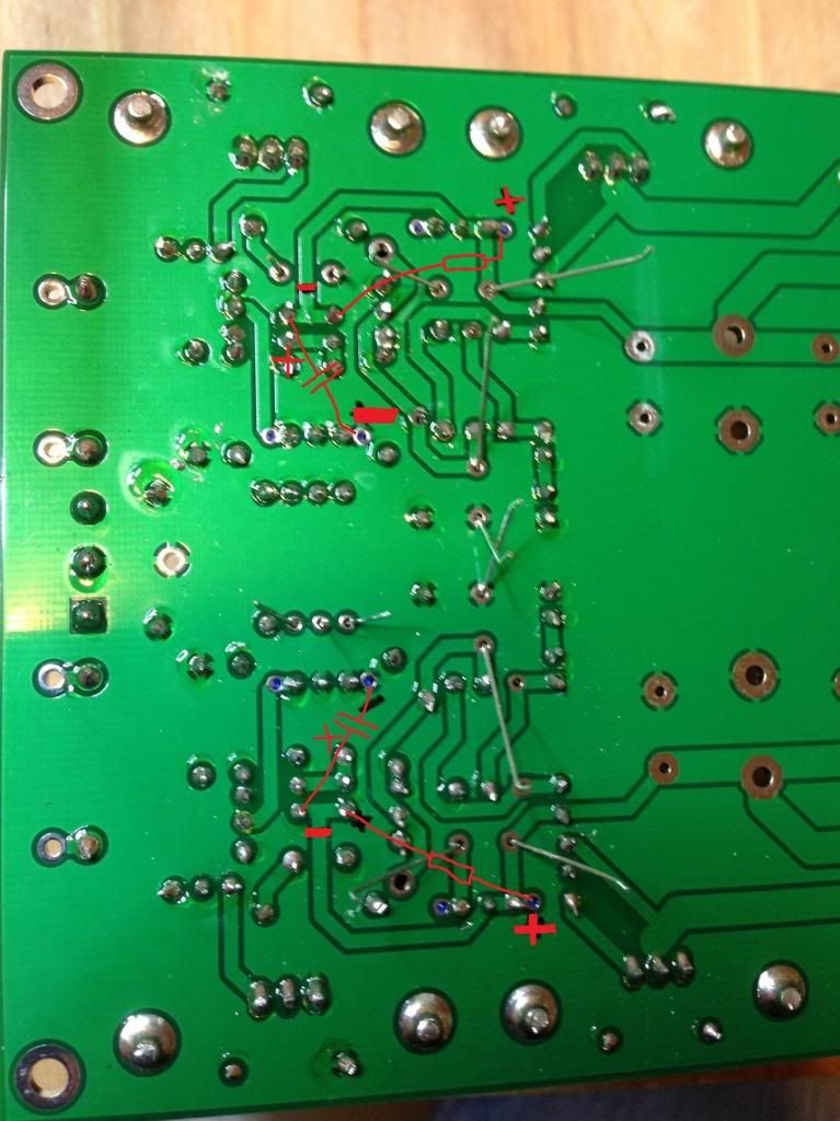
You know, what ever comes handy (at the end of your fingertips) one uses. Did I mark the polarity correctly on the attached picture? I am confused on polarity the polarity of C3B. The 'ground' pins for C3A and C3B face each other, but on the picture in the post #69 the two caps (C3A,C3B) closer to middle of the board appear to be oriented in the same direction. Which approach is correct?  Edited by user Saturday, March 8, 2014 12:23:53 AM(UTC)
| Reason: Not specified File Attachment(s):  Placid BP HD Mod 2.jpg (299kb) downloaded 9 time(s).You cannot view/download attachments. Try to login or register.
|
|
|
|
|
|
Rank: Member
Groups: Member
Joined: 8/22/2010(UTC) Posts: 38  Thanks: 14 times
|
Originally Posted by: DQ828 
Don't tell me that, I just finished the mod :)
Is this what we are suppose to do?
I don't have a Scope to check it :(
Hi: Do the marking in red indicate connection points for the resistors and capacitors (including polarity) correctly? Best regards, 
|
|
|
|
|
|
Rank: Member
Groups: Member
Joined: 6/17/2008(UTC) Posts: 921  Thanks: 1 times
Was thanked: 70 time(s) in 69 post(s)
|
Originally Posted by: dsolodov  Originally Posted by: avr300  Yes certainly, my pleasure.
Panasonic FM 470u, 16v.
You know, what ever comes handy (at the end of your fingertips) one uses. Did I mark the polarity correctly on the attached picture? I am confused on polarity the polarity of C3B. The 'ground' pins for C3A and C3B face each other, but on the picture in the post #69 the two caps (C3A,C3B) closer to middle of the board appear to be oriented in the same direction. Which approach is correct?  No, you're wrong. avr300 attached the following image(s):  cut.JPG (67kb) downloaded 42 time(s).You cannot view/download attachments. Try to login or register.
|
 1 user thanked avr300 for this useful post.
|
|
|
|
Rank: Member
Groups: Member
Joined: 6/17/2008(UTC) Posts: 921  Thanks: 1 times
Was thanked: 70 time(s) in 69 post(s)
|
Originally Posted by: dsolodov  Originally Posted by: DQ828 
Don't tell me that, I just finished the mod :)
Is this what we are suppose to do?
I don't have a Scope to check it :(
Hi: Do the marking in red indicate connection points for the resistors and capacitors (including polarity) correctly? Best regards,  Resistors have no polarity. The cap on the negative side (- side) has to be turned 180 degrees. Remember, when you're dealing with negative polarity, GND is "+" and output is "-". That's why you have mixed up orientation of those caps on the negative half side.
|
 1 user thanked avr300 for this useful post.
|
|
|
|
Rank: Member
Groups: Member
Joined: 8/22/2010(UTC) Posts: 38  Thanks: 14 times
|
Originally Posted by: avr300 
The cap on the negative side (- side) has to be turned 180 degrees.
Remember, when you're dealing with negative polarity, GND is "+" and output is "-". That's why you have mixed up orientation of those caps on the negative half side.
Makes sense. Thank you!
|
|
|
|
|
|
Rank: Member
Groups: Member
Joined: 2/4/2014(UTC) Posts: 42  Thanks: 6 times
Was thanked: 3 time(s) in 3 post(s)
|
If I understand correctly - new Placids will have only a few parts changed compared to previous one?
I just got my placid kits recently and haven't started assembling them yet. Is there a chance I can somehow order new PCBs with a few new parts instead of whole kit once it's available?
|
|
|
|
|
|
Rank: Administration
Groups: Administration, Customer
Joined: 10/24/2006(UTC)
Posts: 2,869
Location: Massachusetts, USA
Thanks: 2 times
Was thanked: 141 time(s) in 134 post(s)
|
Originally Posted by: AlexanderT  If I understand correctly - new Placids will have only a few parts changed compared to previous one?
I just got my placid kits recently and haven't started assembling them yet. Is there a chance I can somehow order new PCBs with a few new parts instead of whole kit once it's available? They are significantly different. The old boards can not be adapted to the new design.
|
|
|
|
|
|
Rank: Member
Groups: Member
Joined: 6/17/2008(UTC) Posts: 921  Thanks: 1 times
Was thanked: 70 time(s) in 69 post(s)
|
That's not the way I read the question.
AlexT has an old kit (board and a bunch of components not yet mounted). Recently bought and not build yet.
He want to buy the new board, adopt the components from the old kit and add the remaining.
That's all comes down to the BOM of the new kit. Time will tell.
|
 1 user thanked avr300 for this useful post.
|
|
|
|
Forum Jump
You cannot post new topics in this forum.
You cannot reply to topics in this forum.
You cannot delete your posts in this forum.
You cannot edit your posts in this forum.
You cannot create polls in this forum.
You cannot vote in polls in this forum.