Rank: Member
Groups: Member
Joined: 1/6/2012(UTC)
Posts: 305
Location: Plainfield, IL
Thanks: 11 times
Was thanked: 26 time(s) in 21 post(s)
|
Originally Posted by: DQ828 
PS: what happened to my 10:4 good buddy :)
I deleted the wrong post I didn't get an answer to, then I deleted the right one. ;) I'll be adding an OTTO to switch between my I2S sources. Thanks for the research. 10:4 good buddy, catch ya on the flip flop. |
|
|
|
|
|
|
Rank: Member
Groups: Member
Joined: 8/17/2010(UTC)
Posts: 368
Location: australia
Thanks: 8 times
Was thanked: 3 time(s) in 3 post(s)
|
Ok, I bet we all hope this is the last word on this subject, I do appreciate all of the help. As far as I can tell my original implementation was as per Leon's guide but this is obviously easier if using am Arduino type control. Leon's guide also say's "The entire OTTO-II module is enabled by connecting 0E to GND. Place a
jumper on 0E to GND." but Russ has said "Don't wire anything to /OE leave it open." so that's what I will do. 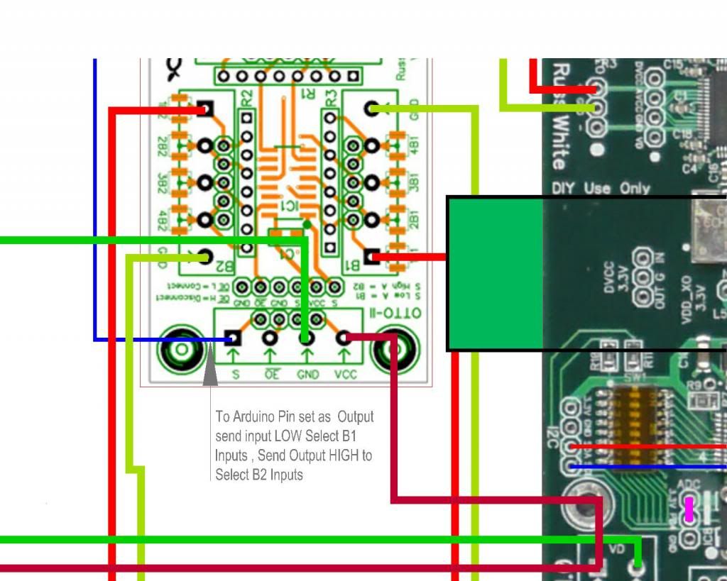 Edited by user Tuesday, February 5, 2013 7:06:39 AM(UTC)
| Reason: Not specified
|
|
|
|
|
|
Rank: Member
Groups: Member
Joined: 1/6/2012(UTC)
Posts: 305
Location: Plainfield, IL
Thanks: 11 times
Was thanked: 26 time(s) in 21 post(s)
|
Originally Posted by: DQ828 
Leon's guide also say's "The entire OTTO-II module is enabled by connecting 0E to GND. Place a
jumper on 0E to GND." but Russ has said "Don't wire anything to /OE leave it open." so that's what I will do.
I am thinking and hope you mean that you still need OE to GND to enable the switch. Don't connect your resistor this way though. 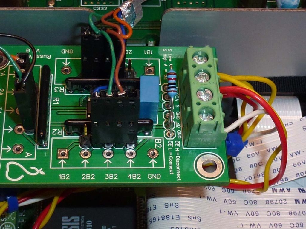 |
|
|
|
|
|
|
Rank: Member
Groups: Member
Joined: 8/17/2010(UTC)
Posts: 368
Location: australia
Thanks: 8 times
Was thanked: 3 time(s) in 3 post(s)
|
Originally Posted by: SCompRacer  Originally Posted by: DQ828 
Leon's guide also say's "The entire OTTO-II module is enabled by connecting 0E to GND. Place a
jumper on 0E to GND." but Russ has said "Don't wire anything to /OE leave it open." so that's what I will do.
I am thinking and hope you mean that you still need OE to GND to enable the switch. Don't connect your resistor this way though.  I have been told I don't need the resistor if I am just sending the Arduino Pin that is connected to "S" High & Low. I think if you are just using a standard toggle switch you need the resistor. As far as the OE goes I'm not sure why Russ says "Don't wire anything to /OE leave it open." but thats what I'm doing, at least for the moment :) At the moment I'm trying to change the code to suit my setup OMG !!! Edited by user Tuesday, February 5, 2013 8:31:35 AM(UTC)
| Reason: Not specified
|
|
|
|
|
|
Rank: Administration
Groups: Administration, Customer
Joined: 10/24/2006(UTC)
Posts: 3,979
Location: Nashville, TN
Thanks: 25 times
Was thanked: 89 time(s) in 83 post(s)
|
That was a mistake on my part. :)
I was looking at the wrong datasheet.
You do need to keep /OE low to enable the outputs.
|
|
|
|
|
|
Rank: Member
Groups: Member
Joined: 8/17/2010(UTC)
Posts: 368
Location: australia
Thanks: 8 times
Was thanked: 3 time(s) in 3 post(s)
|
Thank you, consider it done.
|
|
|
|
|
|
Rank: Administration
Groups: Administration, Customer
Joined: 10/24/2006(UTC)
Posts: 2,869
Location: Massachusetts, USA
Thanks: 2 times
Was thanked: 141 time(s) in 134 post(s)
|
Quote:10:4 good buddy, catch ya on the flip flop. Don't break the gate, Rubber Duck.
|
|
|
|
|
|
Rank: Member
Groups: Member
Joined: 8/17/2010(UTC)
Posts: 368
Location: australia
Thanks: 8 times
Was thanked: 3 time(s) in 3 post(s)
|
So I'm thinking (which is always dangerous) that maybe the S/PDIF/DSD switching can be done without the relay. If I attach an Arduino Pin to the "S" terminal & send it HIGH to select the S/PDIF & LOW to select PCM/DSD, that might work? This is a wild guess & completely leaves out the IP terminal. I have no idea really. http://i1118.photobucket...olSwitch_zpseb614e24.jpg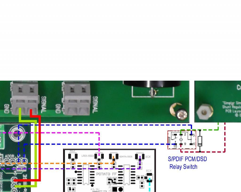 Edited by user Wednesday, February 6, 2013 10:52:57 AM(UTC)
| Reason: Not specified
|
|
|
|
|
|
Rank: Administration
Groups: Administration, Customer
Joined: 10/24/2006(UTC)
Posts: 3,979
Location: Nashville, TN
Thanks: 25 times
Was thanked: 89 time(s) in 83 post(s)
|
You don't need any relays as far as I can see.
IP_S is just an input which you can drive high or low with with the controller. :)
As long as the output driving the IP_S input is < 5V you can drive it directly.
|
|
|
|
|
|
Rank: Member
Groups: Member
Joined: 3/2/2012(UTC)
Posts: 9
Location: USA
|
Originally Posted by: Russ White 
As long as the output driving the IP_S input is < 5V you can drive it directly.
Based on my conversations with Leon, my plan was to connect one of the IP_S pins to ground on the Arduino (by checking the IP_S pins for continuity with common ground on the Buffalo) and then to hook the other IP_S pin up to one of the digital outputs on the Arduino. I would configure that pin as an OUTPUT and send it HIGH/LOW to switch. But given that an Arduino pin puts out around 5V, would it be safer to configure the Arduino pin as an INPUT when you want IP_S to be HIGH and then switch the Arduino pin to be an OUTPUT and set it LOW when you want IP_S to be low? That way you'd never risk sending current over 5V to IP_S.
|
|
|
|
|
|
Rank: Administration
Groups: Administration, Customer
Joined: 10/24/2006(UTC)
Posts: 3,979
Location: Nashville, TN
Thanks: 25 times
Was thanked: 89 time(s) in 83 post(s)
|
IP_S is a high impedance input, and it does not directly go to the DAC. It can take up to 5V with no issues. techincally it can take up to VD - but 5V is a good safe guideline as VD should always be more than that. :) Edited by user Wednesday, February 6, 2013 7:10:22 PM(UTC)
| Reason: Not specified
|
|
|
|
|
|
Rank: Member
Groups: Member
Joined: 8/17/2010(UTC)
Posts: 368
Location: australia
Thanks: 8 times
Was thanked: 3 time(s) in 3 post(s)
|
Have I got this right.
I check the S & IP pins to see which goes to ground, whichever one goes to ground I link to Arduino Grnd
Then the other pin is connected to the Arduino Pin set as output & drive it high or low to switch.
|
|
|
|
|
|
Rank: Administration
Groups: Administration, Customer
Joined: 10/24/2006(UTC)
Posts: 2,869
Location: Massachusetts, USA
Thanks: 2 times
Was thanked: 141 time(s) in 134 post(s)
|
Originally Posted by: DQ828  Have I got this right.
I check the S & IP pins to see which goes to ground, whichever one goes to ground I link to Arduino Grnd
Then the other pin is connected to the Arduino Pin set as output & drive it high or low to switch. Correct. If you are already sharing a ground betwen the Buffalo and the Arduino, then you do not need to make the additional ground connection.
|
|
|
|
|
|
Rank: Member
Groups: Member
Joined: 8/17/2010(UTC)
Posts: 368
Location: australia
Thanks: 8 times
Was thanked: 3 time(s) in 3 post(s)
|
What am I going to do with all these left over relays :) Add them to the pile i guess
Thanks always
|
|
|
|
|
|
Rank: Member
Groups: Member
Joined: 8/17/2010(UTC)
Posts: 368
Location: australia
Thanks: 8 times
Was thanked: 3 time(s) in 3 post(s)
|
So the IP terminal is linked to ground & yes I already have the BII SE linked to the Arduino ground so all I need is the Arduino pin connected to the "S" terminal. You know I'm starting to think this think might be done, or at least very close. I'd better pull my finger out & put it all together. 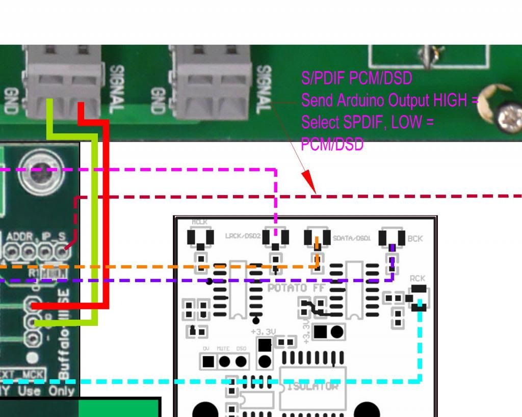
|
|
|
|
|
|
Rank: Member
Groups: Member
Joined: 8/17/2010(UTC)
Posts: 368
Location: australia
Thanks: 8 times
Was thanked: 3 time(s) in 3 post(s)
|
Well I'll be damned, I got the modified code to compile  Of course that doesn't mean it will work.
|
|
|
|
|
|
Rank: Member
Groups: Member
Joined: 8/17/2010(UTC)
Posts: 368
Location: australia
Thanks: 8 times
Was thanked: 3 time(s) in 3 post(s)
|
I've made the prototype board the same size as the planned internal dimensions of the final build. I have soldered header pins onto most of the Mega pins that aren't being used by the screen and made the bracket so they can be easily accessed. 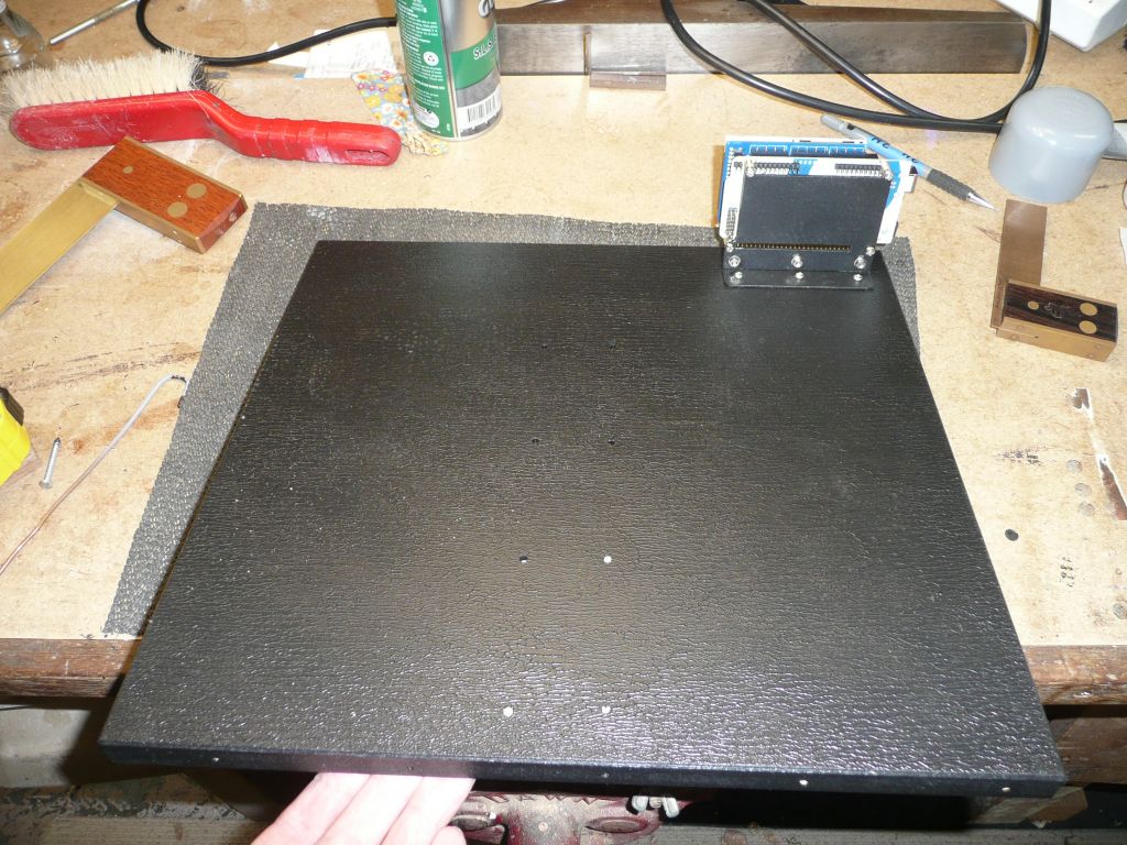 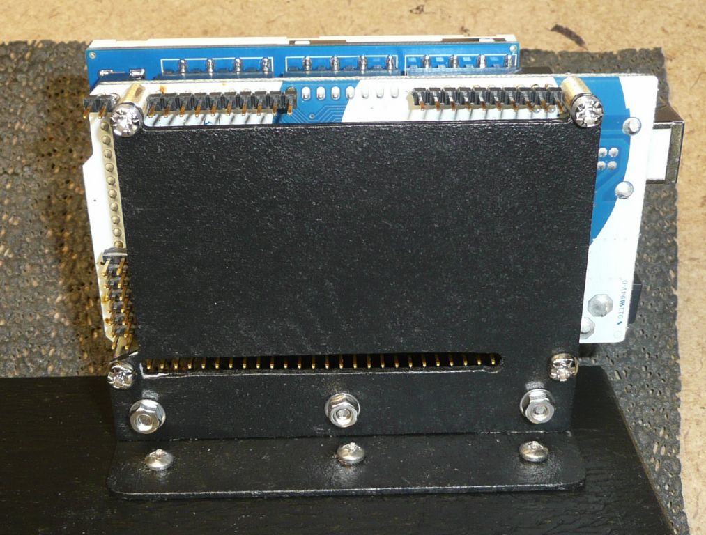 I haven't had a lot of time in the last couple of days but have got a start. first the pile ready for transformation 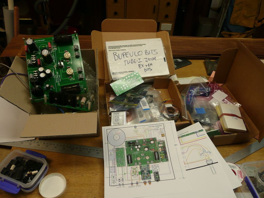 I thought I'd at least make the prototype look a bit better as they seem to stay prototypes for a while I bought some Duratex & thought I'd give it a go on the base board, seems like a good product that may come in handy. It's a very tough water base texture coat. Actually I coated everything in it :) 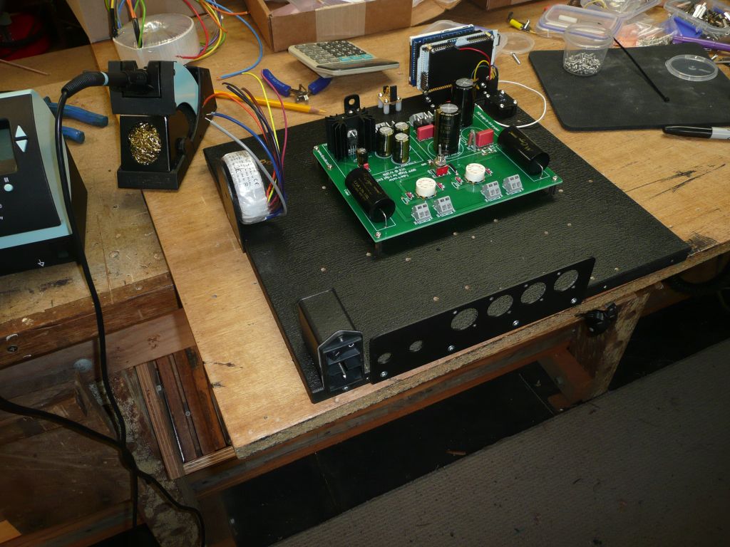 The IR Receiver 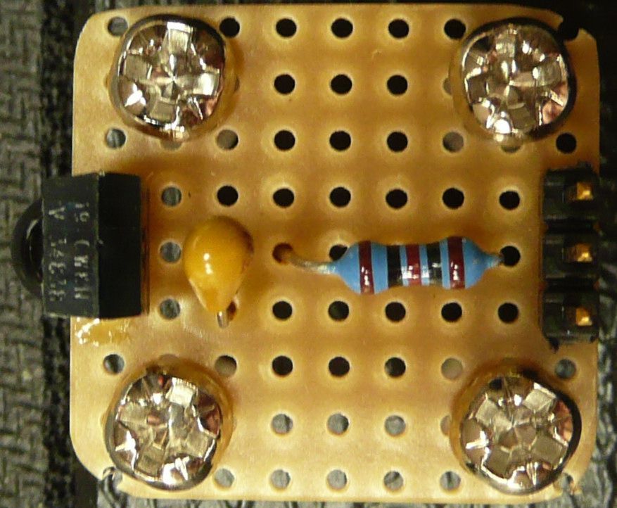 The De-bounce thingy 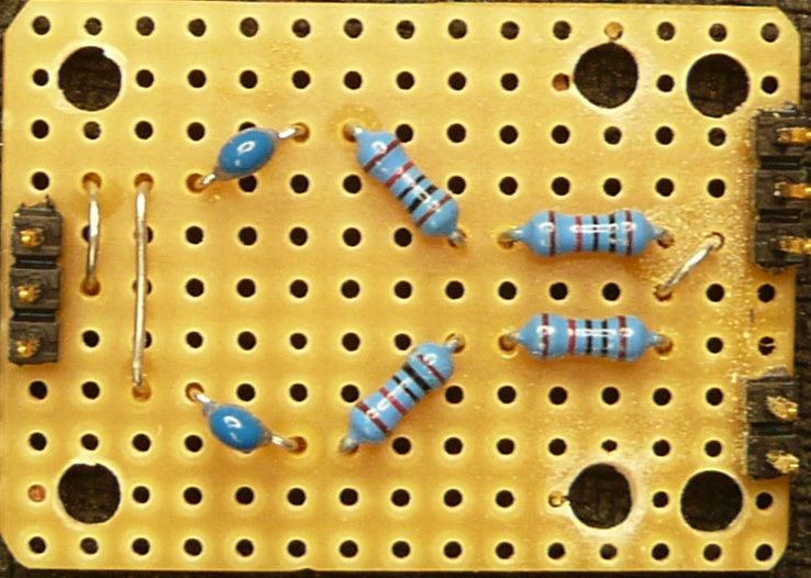 No time tomorrow I'm afraid :( Edited by user Saturday, February 9, 2013 10:41:13 AM(UTC)
| Reason: Not specified
|
|
|
|
|
|
Rank: Member
Groups: Member
Joined: 1/6/2012(UTC)
Posts: 305
Location: Plainfield, IL
Thanks: 11 times
Was thanked: 26 time(s) in 21 post(s)
|
Originally Posted by: DQ828  Well I'll be damned, I got the modified code to compile  Of course that doesn't mean it will work. Remember that TV show Fantasy Island? I used to wake up at night with Tattoo screaming in my ear "De Code, De Code!" Great progress! Nice work too. I like your prototype board more than my friendly case (the ones that wave at you). If you haven't already, make sure you modify the code for hardware debounce. |
|
|
|
|
|
|
Rank: Member
Groups: Member
Joined: 8/17/2010(UTC)
Posts: 368
Location: australia
Thanks: 8 times
Was thanked: 3 time(s) in 3 post(s)
|
Originally Posted by: SCompRacer  Originally Posted by: DQ828  Well I'll be damned, I got the modified code to compile  Of course that doesn't mean it will work. Remember that TV show Fantasy Island? I used to wake up at night with Tattoo screaming in my ear "De Code, De Code!" Great progress! Nice work too. I like your prototype board more than my friendly case (the ones that wave at you). If you haven't already, make sure you modify the code for hardware debounce. The change I made was to set the Vol up & down pin LOW, I assume that's what you where getting at? The thing I'm not sure about is whether I need to make any changes to the DAC registers for the BIII SE, I looked at Leon's guide but still wasn't sure. Edited by user Sunday, February 10, 2013 8:45:44 AM(UTC)
| Reason: Not specified
|
|
|
|
|
|
Rank: Member
Groups: Member
Joined: 1/6/2012(UTC)
Posts: 305
Location: Plainfield, IL
Thanks: 11 times
Was thanked: 26 time(s) in 21 post(s)
|
Originally Posted by: DQ828 
The change I made was to set the Vol up & down pin LOW, I assume that's what you where getting at?
Thats it. Not sure about the registers. It's the same chip so all I could do is hazard a guess they are the same...but I also know what guessing can get you in diy. |
|
|
|
|
|
|
Forum Jump
You cannot post new topics in this forum.
You cannot reply to topics in this forum.
You cannot delete your posts in this forum.
You cannot edit your posts in this forum.
You cannot create polls in this forum.
You cannot vote in polls in this forum.