Rank: Member
Groups: Member
Joined: 2/1/2012(UTC)
Posts: 332
Location: The Netherlands
Thanks: 4 times
Was thanked: 18 time(s) in 18 post(s)
|
That's possible, but you need just one Mega pin. Use a NPN transistor as switch driven by the mega pin. The coil's operating current is 40mA. That's the same as the Mega pin can source and can easily damage the Mega. When using a transistor (in a similar way as the sidecar) it has to source only around 1mA, depending on the used resistor (Rb). RL is the relay. Do use the flyback (protection) diode. You need to calculate Rb. Where: collector current = 0.040 A (Relay's coil current) Hfe = depends on the used transistor Supply voltage = 5V (from Mega pin) voltage drop = depends on the used transistor http://kaizerpowerelectr...ase-resistor-calculator/Corpius attached the following image(s):  trswinpn.gif (4kb) downloaded 39 time(s).You cannot view/download attachments. Try to login or register. |
|
|
|
|
|
|
Rank: Member
Groups: Member
Joined: 8/17/2010(UTC)
Posts: 368
Location: australia
Thanks: 8 times
Was thanked: 3 time(s) in 3 post(s)
|
Originally Posted by: Corpius  That's possible, but you need just one Mega pin. Use a NPN transistor as switch driven by the mega pin. The coil's operating current is 40mA. That's the same as the Mega pin can source and can easily damage the Mega. When using a transistor (in a similar way as the sidecar) it has to source only around 1mA, depending on the used resistor (Rb). RL is the relay. Do use the flyback (protection) diode. You need to calculate Rb. Where: collector current = 0.040 A (Relay's coil current) Hfe = depends on the used transistor Supply voltage = 5V (from Mega pin) voltage drop = depends on the used transistor http://kaizerpowerelectr...ase-resistor-calculator/ Sorry I don't understand how the setup operates the latching function which requires the polarity reversed on the 5v input to switch the relay. Of course I could use the http://au.mouser.com/Pro...81oJCrqXXzxNQP%2fcYSA%3d which should look familiar and only consumes 21mA.
|
|
|
|
|
|
Rank: Administration
Groups: Administration, Customer
Joined: 10/24/2006(UTC)
Posts: 2,869
Location: Massachusetts, USA
Thanks: 2 times
Was thanked: 141 time(s) in 134 post(s)
|
Originally Posted by: DQ828 Sorry I don't understand how the setup operates the latching function which requires the polarity reversed on the 5v input to switch the relay. Of course I could use the http://au.mouser.com/Pro...81oJCrqXXzxNQP%2fcYSA%3d which should look familiar and only consumes 21mA. That circuit does not handle latching relays. The G6K is a better relay for this purpose anyway (made fore telecom signal switching, smaller, lower current). Or just use an OTTO-II. :)
|
|
|
|
|
|
Rank: Administration
Groups: Administration, Customer
Joined: 10/24/2006(UTC)
Posts: 3,979
Location: Nashville, TN
Thanks: 25 times
Was thanked: 89 time(s) in 83 post(s)
|
If you use OTTO-II you need no driver circuit at all :)
|
|
|
|
|
|
Rank: Member
Groups: Member
Joined: 8/17/2010(UTC)
Posts: 368
Location: australia
Thanks: 8 times
Was thanked: 3 time(s) in 3 post(s)
|
Ok, I saw the light & ordered an OTTO :) Edited by user Friday, January 18, 2013 9:58:58 PM(UTC)
| Reason: Not specified
|
|
|
|
|
|
Rank: Member
Groups: Member
Joined: 2/1/2012(UTC)
Posts: 332
Location: The Netherlands
Thanks: 4 times
Was thanked: 18 time(s) in 18 post(s)
|
Originally Posted by: DQ828 Ok, I saw the light & ordered an OTTO :) The easiest and probably best solution :) btw I did not saw that the relay you mentioned was a latching type.  Oh well you don't need it anyway... |
|
|
|
|
|
|
Rank: Member
Groups: Member
Joined: 8/17/2010(UTC)
Posts: 368
Location: australia
Thanks: 8 times
Was thanked: 3 time(s) in 3 post(s)
|
I've been going around in circles drawing layouts for the new DAC and was hoping that you guy's might give me some advice on the best layout. I have had input from various DIY guy's and applied there suggestions to the layouts as I have progressed. At this stage I think layout 4 is probably the go the only downside I can see is the distance the Arduino Mega is from the BIISE. I do want to leave the Mega where it is, assuming the distance is not a communications issue, which I don't think it is. 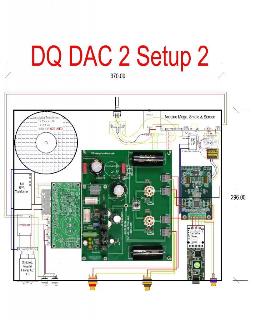 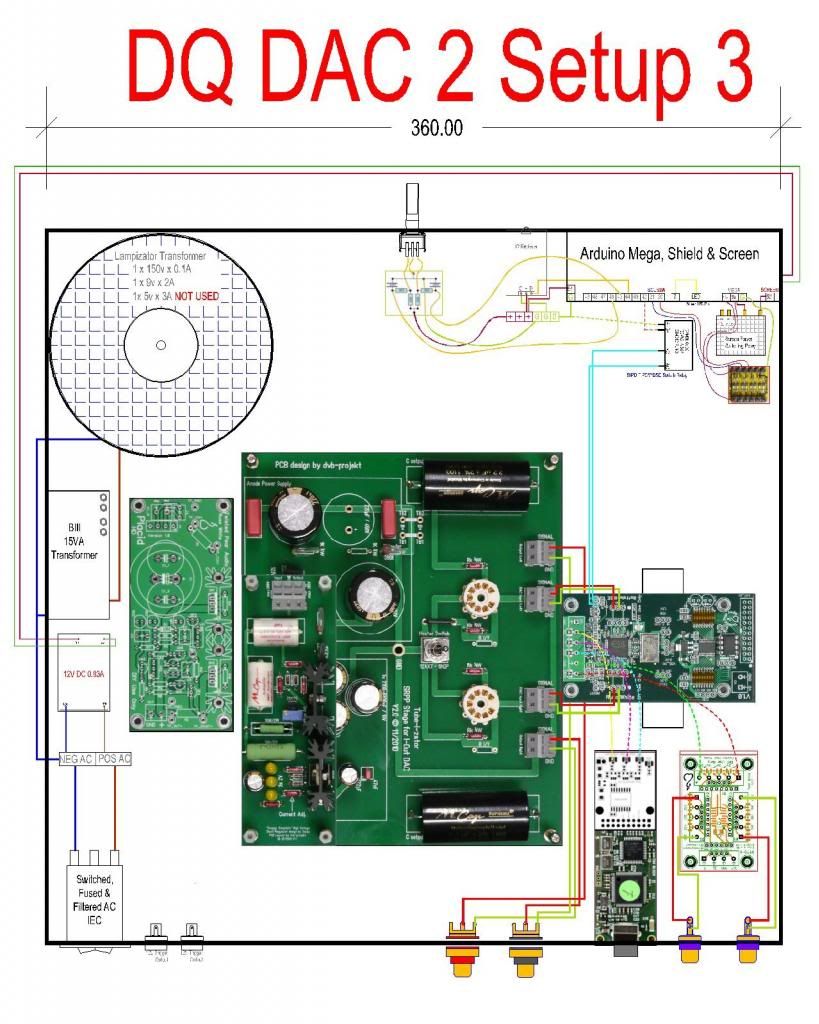 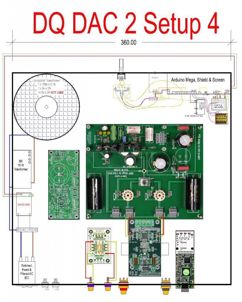
|
|
|
|
|
|
Rank: Member
Groups: Member
Joined: 1/6/2012(UTC)
Posts: 305
Location: Plainfield, IL
Thanks: 11 times
Was thanked: 26 time(s) in 21 post(s)
|
High marks on your planning skills! My I2C wires are 13" (330mm) long measured between the connectors. I estimate yours would be ~18" (457mm)? That would be using nice right angle bends (not strung above and across the tube board  ). Not sure what a max length would be. I've never encountered any control issues with mine. If you don't get a max length answer and decide on a length, I'd make one to test for you. Edited by user Monday, January 21, 2013 3:19:46 AM(UTC)
| Reason: Not specified |
|
|
|
|
|
|
Rank: Administration
Groups: Administration, Customer
Joined: 10/24/2006(UTC)
Posts: 3,979
Location: Nashville, TN
Thanks: 25 times
Was thanked: 89 time(s) in 83 post(s)
|
Long I2C lines are no problem. Just keep the PS/PCM/Analog lines short.
|
|
|
|
|
|
Rank: Member
Groups: Member
Joined: 8/17/2010(UTC)
Posts: 368
Location: australia
Thanks: 8 times
Was thanked: 3 time(s) in 3 post(s)
|
Originally Posted by: SCompRacer High marks on your planning skills! My I2C wires are 13" (330mm) long measured between the connectors. I estimate yours would be ~18" (457mm)? That would be using nice right angle bends (not strung above and across the tube board ). Not sure what a max length would be. I've never encountered any control issues with mine. If you don't get a max length answer and decide on a length, I'd make one to test for you. It will between 450 & 500mm long. Thanks for the offer of the test but I expect it should work fine from what Russ said & some of the other reading I have been doing. I am now on version 5 even though it's still called version 4 as I had a brain explosion and forgot I couldnt have the High Voltage Shunt Regulator mounted above the TubeIzator due to my lack of headroom  I will do some more work on the design & then post it again. Thanks for the help you to Russ
|
|
|
|
|
|
Rank: Member
Groups: Member
Joined: 8/17/2010(UTC)
Posts: 368
Location: australia
Thanks: 8 times
Was thanked: 3 time(s) in 3 post(s)
|
It's been recommended that I connect the Tube_I_Zator ground point to the case star ground, which I assume is the Earth Point. Should the BIIISE be connected to the star ground point somehow? I will say, in the whole catastrophe (see photo) which includes the BIII, (not BIIISE) Arduino control setup & Linkwitz ASP crossovers, only one power supply is connected to earth & everything runs fine. But eventually they will all go in separate cases that may make a difference. 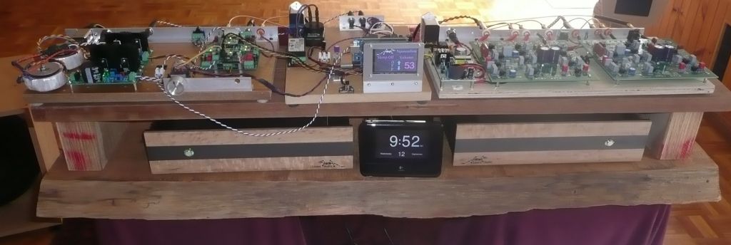 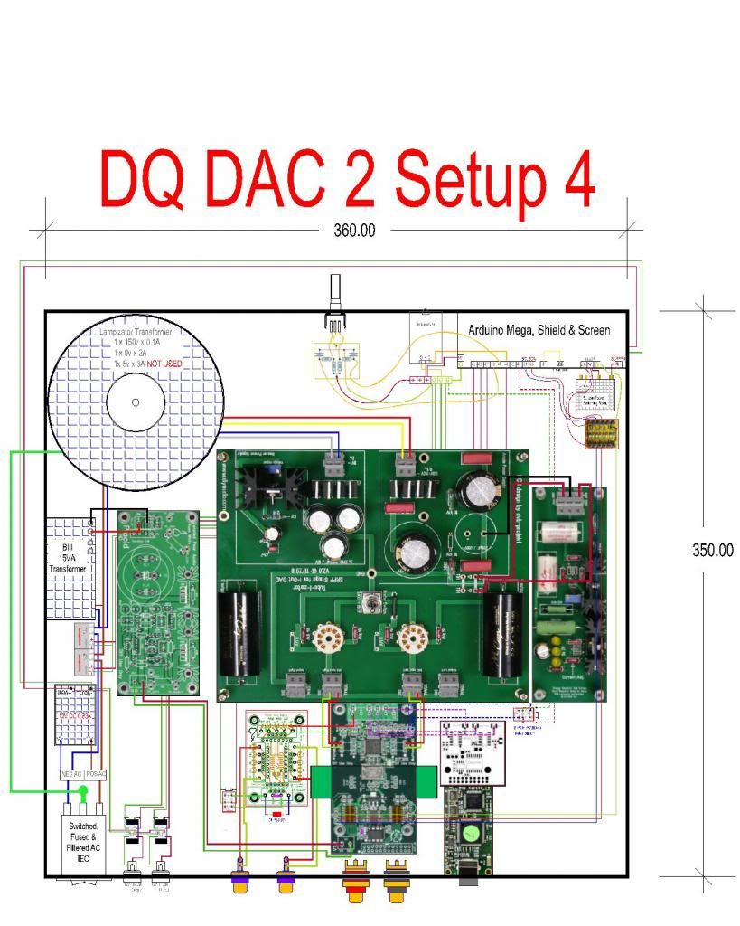
|
|
|
|
|
|
Rank: Member
Groups: Member
Joined: 1/6/2012(UTC)
Posts: 305
Location: Plainfield, IL
Thanks: 11 times
Was thanked: 26 time(s) in 21 post(s)
|
Originally Posted by: DQ828 It's been recommended that I connect the Tube_I_Zator ground point to the case star ground, which I assume is the Earth Point.
Should the BIIISE be connected to the star ground point somehow?
I use a star ground for my BIII boards, power supplies and modules per Russ's recommendation but was under the understanding that those grounds should not be connected to chassis earth ground. I used a ring terminal (ground wires soldered to it) and attached it to a plastic standoff. Edited by user Friday, January 25, 2013 12:09:02 AM(UTC)
| Reason: Not specified |
|
|
|
|
|
|
Rank: Member
Groups: Member
Joined: 8/17/2010(UTC)
Posts: 368
Location: australia
Thanks: 8 times
Was thanked: 3 time(s) in 3 post(s)
|
Originally Posted by: SCompRacer Originally Posted by: DQ828 It's been recommended that I connect the Tube_I_Zator ground point to the case star ground, which I assume is the Earth Point.
Should the BIIISE be connected to the star ground point somehow?
I use a star ground for my BIII boards, power supplies and modules per Russ's recommendation but was under the understanding that those grounds should not be connected to chassis earth ground. I used a ring terminal (ground wires soldered to it) and attached it to a plastic standoff. What point on the BIII did you connect to ground or can you just connect any ground point? Is the Arduino connected to the same star ground? Or do you do a separate star ground for the control side? Any idea if my Otto looks wired correctly 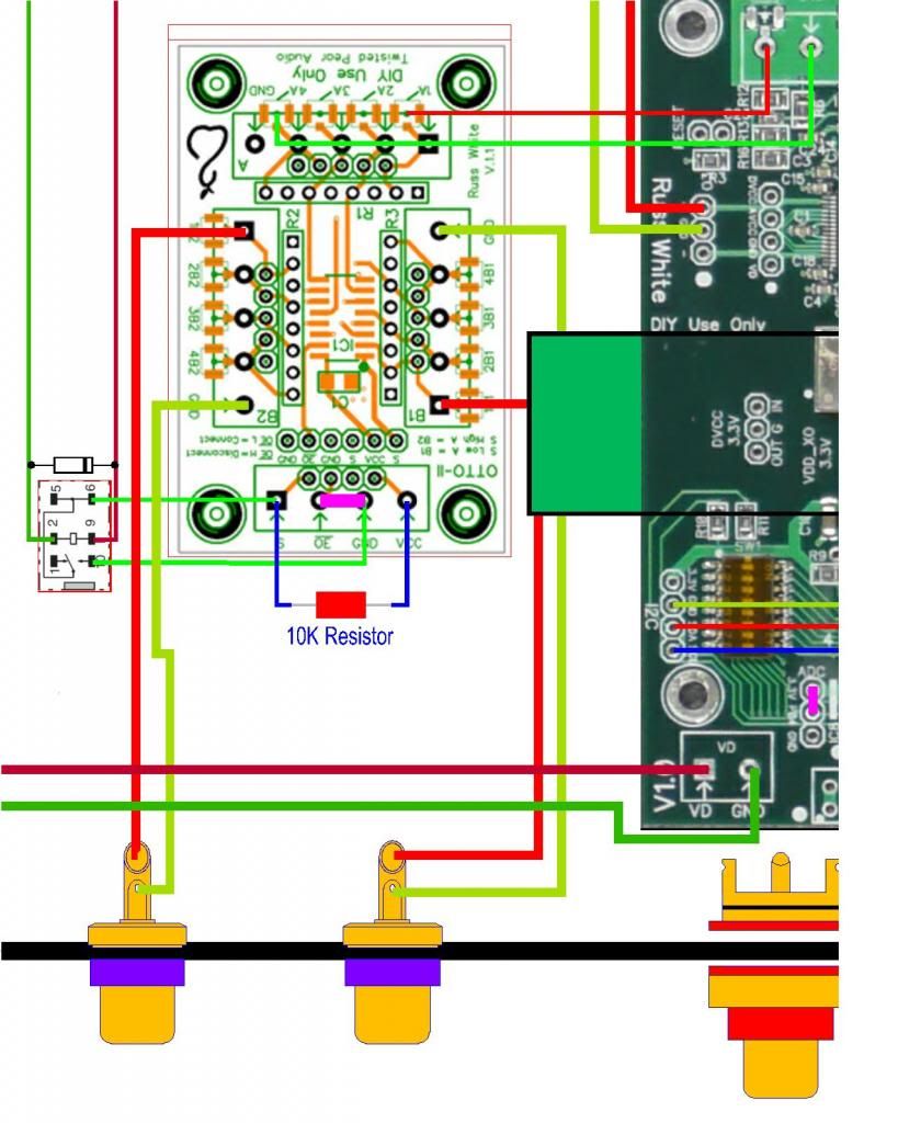 Edited by user Friday, January 25, 2013 1:10:29 AM(UTC)
| Reason: Not specified
|
|
|
|
|
|
Rank: Member
Groups: Member
Joined: 1/6/2012(UTC)
Posts: 305
Location: Plainfield, IL
Thanks: 11 times
Was thanked: 26 time(s) in 21 post(s)
|
BIII ground (next to power in) to star ground. Only other ground would be through board pads on metal standoffs?
I did not attach the Arduino GND to the star ground, it connects to the LCBPS GND.
I also attached the I2C GND to the BIII master board header. I had it connected to the star GND at one time and did not notice any operational changes.
Your OTTO looks correct to me. |
|
|
|
|
|
|
Rank: Member
Groups: Member
Joined: 8/17/2010(UTC)
Posts: 368
Location: australia
Thanks: 8 times
Was thanked: 3 time(s) in 3 post(s)
|
|
|
|
|
|
|
Rank: Member
Groups: Member
Joined: 2/1/2012(UTC)
Posts: 332
Location: The Netherlands
Thanks: 4 times
Was thanked: 18 time(s) in 18 post(s)
|
Originally Posted by: SCompRacer BIII ground (next to power in) to star ground. Only other ground would be through board pads on metal standoffs?
I did not attach the Arduino GND to the star ground, it connects to the LCBPS GND.
I also attached the I2C GND to the BIII master board header. I had it connected to the star GND at one time and did not notice any operational changes.
Your OTTO looks correct to me. You can connect the Arduino to the star ground just like you connected all other modules to it and eliminate the I2C gnd to the BIII master board header. This should rule out any possible ground loops. Another option to avoid possible ground loops and noise is to isolate the arduino completely from the DAC by using an I2C isolator (ADUM1250 or similar), like I have done recently. The switching of the sidecar / OTTO must be isolated too in order to retain complete isolation. Some SSR's or ESR's can be used to achieve this. |
|
|
|
|
|
|
Rank: Member
Groups: Member
Joined: 8/17/2010(UTC)
Posts: 368
Location: australia
Thanks: 8 times
Was thanked: 3 time(s) in 3 post(s)
|
I2C Ground removal & Arduino Ground to star ground I'm still pondering the other suggestions 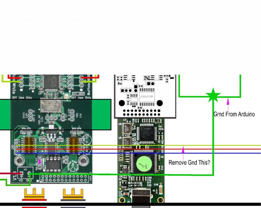
|
|
|
|
|
|
Rank: Member
Groups: Member
Joined: 2/1/2012(UTC)
Posts: 332
Location: The Netherlands
Thanks: 4 times
Was thanked: 18 time(s) in 18 post(s)
|
Yes, remove that gnd connection. I think it is best to put the star ground between the power supply and the module powered by the supply. So a single gnd connection from each power supply to the ground star and from there a single gnd connection to each module. Your image shows the star ground in a different position. - Edited by user Friday, January 25, 2013 1:17:13 PM(UTC)
| Reason: Not specified |
|
|
|
|
|
|
Rank: Member
Groups: Member
Joined: 8/17/2010(UTC)
Posts: 368
Location: australia
Thanks: 8 times
Was thanked: 3 time(s) in 3 post(s)
|
Originally Posted by: Corpius Yes, remove that gnd connection.
I think it is best to put the star ground between the power supply and the module powered by the supply. So a single gnd connection from each power supply to the ground star and from there a single gnd connection to each module. Your image shows the star ground in a different position.
- Do you mean like this. Interestingly nothing is grounded together on my existing setup & it all works fine, no hum no buzz. 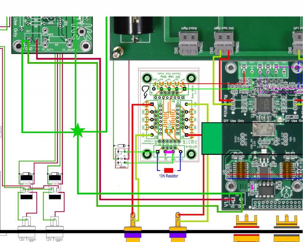
|
|
|
|
|
|
Rank: Member
Groups: Member
Joined: 2/1/2012(UTC)
Posts: 332
Location: The Netherlands
Thanks: 4 times
Was thanked: 18 time(s) in 18 post(s)
|
Almost, I removed the ground connection between the placid and the DAC (see image). Your last image stills shows two gnd lines between placid and DAC. When removing the connection the current will flow back to the star ground and it will find its way from there. Connect all other modules the same way to the same star ground. Edited by user Friday, January 25, 2013 11:08:52 PM(UTC)
| Reason: Not specified Corpius attached the following image(s): Start ground.jpg (217kb) downloaded 52 time(s).You cannot view/download attachments. Try to login or register. |
|
|
|
|
|
|
Forum Jump
You cannot post new topics in this forum.
You cannot reply to topics in this forum.
You cannot delete your posts in this forum.
You cannot edit your posts in this forum.
You cannot create polls in this forum.
You cannot vote in polls in this forum.

