Rank: Member
Groups: Member
Joined: 1/6/2012(UTC)
Posts: 305
Location: Plainfield, IL
Thanks: 11 times
Was thanked: 26 time(s) in 21 post(s)
|
I'm gonna leave everything as is.....no problems, absolutely dead quiet. ;) After fixing the Krell KSL phono board problems I'm not gonna give the audio gods a chance to get back at me....they allowed me to remove 23 transistors/jfets to test that are no longer in production and reinstall them unharmed. They think I owe em now..... Edited by user Friday, January 25, 2013 11:30:02 PM(UTC)
| Reason: Not specified |
|
|
|
|
|
|
Rank: Administration
Groups: Administration, Customer
Joined: 10/24/2006(UTC)
Posts: 3,979
Location: Nashville, TN
Thanks: 25 times
Was thanked: 89 time(s) in 83 post(s)
|
There is no need for an elaborate star ground. :)
|
|
|
|
|
|
Rank: Member
Groups: Member
Joined: 8/17/2010(UTC)
Posts: 368
Location: australia
Thanks: 8 times
Was thanked: 3 time(s) in 3 post(s)
|
Originally Posted by: SCompRacer  I'm gonna leave everything as is.....no problems, absolutely dead quiet. ;)
After fixing the Krell KSL phono board problems I'm not gonna give the audio gods a chance to get back at me....they allowed me to remove 23 transistors/jfets to test that are no longer in production and reinstall them unharmed. They think I owe em now..... If it aint broke don't fix it 
|
|
|
|
|
|
Rank: Member
Groups: Member
Joined: 2/1/2012(UTC)
Posts: 332
Location: The Netherlands
Thanks: 4 times
Was thanked: 18 time(s) in 18 post(s)
|
Originally Posted by: DQ828  If it aint broke don't fix it  Try telling that to a DIY enthusiast  |
|
|
|
|
|
|
Rank: Member
Groups: Member
Joined: 8/17/2010(UTC)
Posts: 368
Location: australia
Thanks: 8 times
Was thanked: 3 time(s) in 3 post(s)
|
For the life of me I cannot workout how to add a remote control function in the HiFiduino code. The remote only seems to use the Up, Down & Center Buttons. I cannot work out how the HiFiduino code applies the remote code once it has been received. The way the coding for the remote is done is completely different to the way it is implemented in my code for my first DAC, but I would like to use this code if I can work out how to change it. I want to add a function to the Remote's Right Arrow to switch between sources, I will just make is sequential as I only have 3 inputs , I don't think I will need to write to the registers only switch the relays to control the Otto & switch between the DSD & Spdif inputs. I would also like to make the Menu key the Power On Power Off key, this would control the relays that switch the DAC & the 12v triggers on. Any help would be GREATLY appreciated. After looking at Dim Dim's code things are a bit clearer, except the link between the receiving of the code & how the code is applied to the specific function. Edited by user Friday, February 1, 2013 11:59:28 AM(UTC)
| Reason: Not specified
|
|
|
|
|
|
Rank: Member
Groups: Member
Joined: 2/1/2012(UTC)
Posts: 332
Location: The Netherlands
Thanks: 4 times
Was thanked: 18 time(s) in 18 post(s)
|
I'll help you. If you send me a PM with your email address, I can send you mine. Then send me your code and I will have a look at it. Can you describe which sources you have and how you connected them (including relays, OTTO's or other switching devices) ? I need to know this in order to work out how the switching should be done. |
|
|
|
|
|
|
Rank: Administration
Groups: Administration, Customer
Joined: 10/24/2006(UTC)
Posts: 2,869
Location: Massachusetts, USA
Thanks: 2 times
Was thanked: 141 time(s) in 134 post(s)
|
This may have already been discussed, but why are you using a relay to trigger the OTTO?
|
|
|
|
|
|
Rank: Member
Groups: Member
Joined: 8/17/2010(UTC)
Posts: 368
Location: australia
Thanks: 8 times
Was thanked: 3 time(s) in 3 post(s)
|
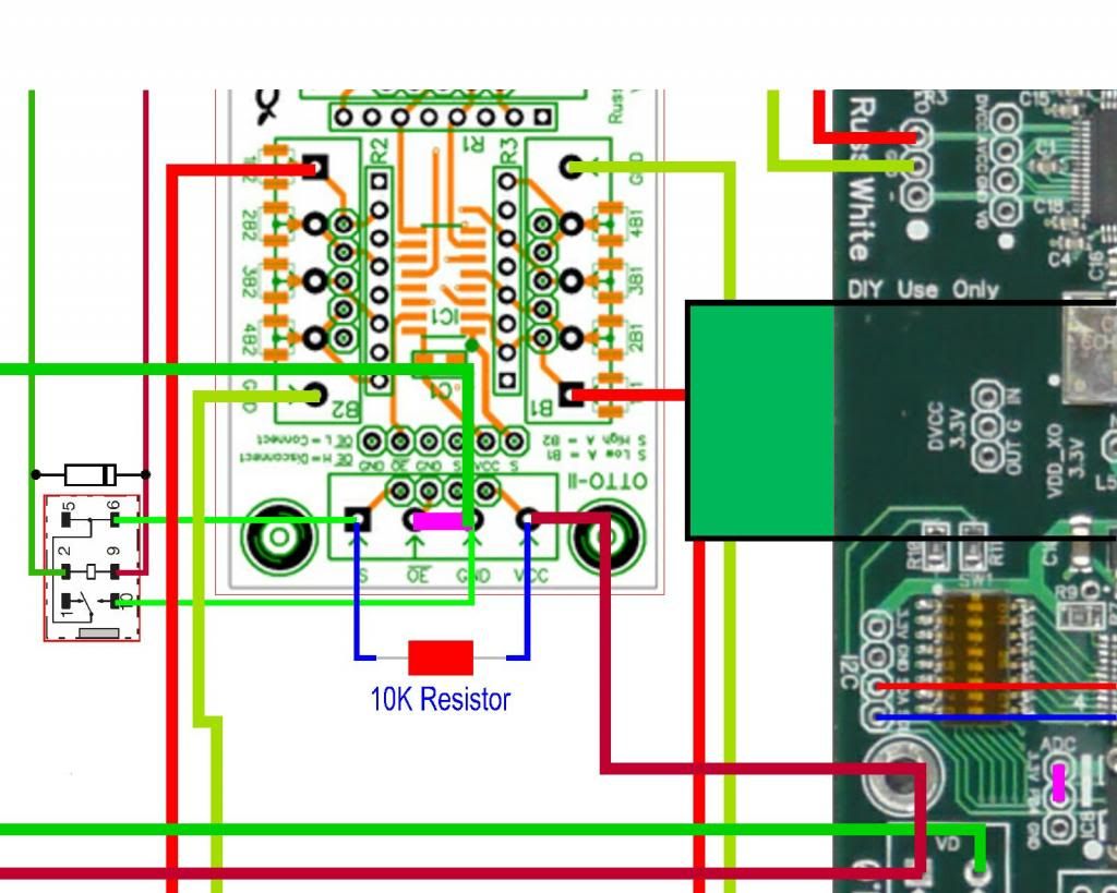
Originally Posted by: Brian Donegan  This may have already been discussed, but why are you using a relay to trigger the OTTO? Cause that's what I thought I was suppose to do :) I assume you've seen the drawing on the previous page of the setup I planning to use, the relay is just a switch like in Leon's guide. Edited by user Friday, February 1, 2013 9:50:01 PM(UTC)
| Reason: Not specified
|
|
|
|
|
|
Rank: Administration
Groups: Administration, Customer
Joined: 10/24/2006(UTC)
Posts: 3,979
Location: Nashville, TN
Thanks: 25 times
Was thanked: 89 time(s) in 83 post(s)
|
No need for the relay. :)
|
|
|
|
|
|
Rank: Member
Groups: Member
Joined: 2/1/2012(UTC)
Posts: 332
Location: The Netherlands
Thanks: 4 times
Was thanked: 18 time(s) in 18 post(s)
|
Except if he want to fully isolate the DAC from the Arduino, but then he would need an I2C isolator too. |
|
|
|
|
|
|
Rank: Administration
Groups: Administration, Customer
Joined: 10/24/2006(UTC)
Posts: 3,979
Location: Nashville, TN
Thanks: 25 times
Was thanked: 89 time(s) in 83 post(s)
|
Much more important things to worry over.
|
|
|
|
|
|
Rank: Member
Groups: Member
Joined: 11/9/2007(UTC)
Posts: 453
Location: usa
|
Originally Posted by: DQ828  For the life of me I cannot workout how to add a remote control function in the HiFiduino code. The remote only seems to use the Up, Down & Center Buttons. I cannot work out how the HiFiduino code applies the remote code once it has been received. The way the coding for the remote is done is completely different to the way it is implemented in my code for my first DAC, but I would like to use this code if I can work out how to change it.
I want to add a function to the Remote's Right Arrow to switch between sources, I will just make is sequential as I only have 3 inputs , I don't think I will need to write to the registers only switch the relays to control the Otto & switch between the DSD & Spdif inputs.
I would also like to make the Menu key the Power On Power Off key, this would control the relays that switch the DAC & the 12v triggers on.
Any help would be GREATLY appreciated.
After looking at Dim Dim's code things are a bit clearer, except the link between the receiving of the code & how the code is applied to the specific function. Add a case statement for the keys you want to control. The "remote code detector" code returns the value of the key you press.
|
|
|
|
|
|
Rank: Member
Groups: Member
Joined: 8/17/2010(UTC)
Posts: 368
Location: australia
Thanks: 8 times
Was thanked: 3 time(s) in 3 post(s)
|
Originally Posted by: Russ White  No need for the relay. :) Would you like to elaborate? I realised I changed the wiring since the last pic was posted, I have connected the Placid 5v to the OTTO VCC, I assume this is wrong?  Edited by user Saturday, February 2, 2013 11:28:02 AM(UTC)
| Reason: Not specified
|
|
|
|
|
|
Rank: Administration
Groups: Administration, Customer
Joined: 10/24/2006(UTC)
Posts: 3,979
Location: Nashville, TN
Thanks: 25 times
Was thanked: 89 time(s) in 83 post(s)
|
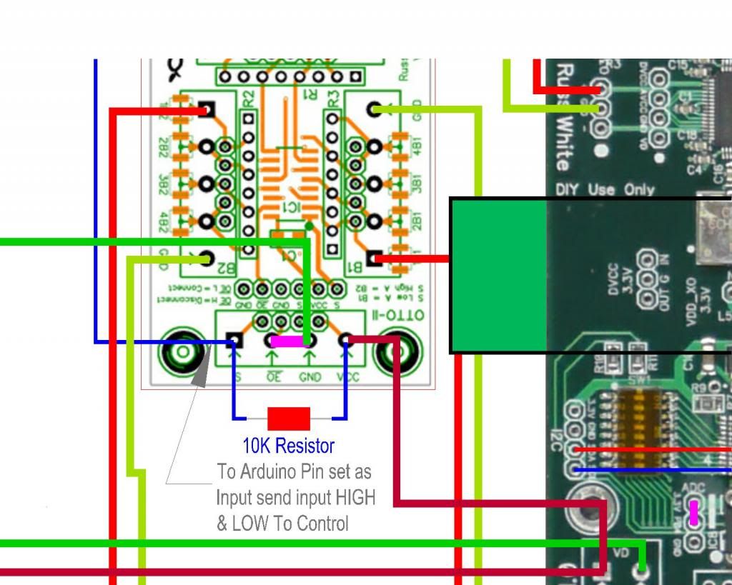
All you need to do is connect S to a controller output pin (in open drain mode is fine since the is a pull-up R - driven mode is fine too).
|
|
|
|
|
|
Rank: Member
Groups: Member
Joined: 8/17/2010(UTC)
Posts: 368
Location: australia
Thanks: 8 times
Was thanked: 3 time(s) in 3 post(s)
|
How's this look.  I'm not exactly sure what this meant "since the is a pull-up R"Can you confirm the OTTO VCC is ok connected to the Placid via the BIII SE as per the drawing. Many thanks DQ
|
|
|
|
|
|
Rank: Administration
Groups: Administration, Customer
Joined: 10/24/2006(UTC)
Posts: 3,979
Location: Nashville, TN
Thanks: 25 times
Was thanked: 89 time(s) in 83 post(s)
|
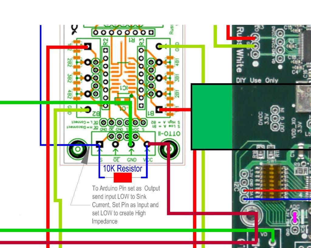
The 10K is a pullup resistor. That means your micontroller does not need to drive it high. Only *needs* go open drain. Google open drain output.
Active output is also still fine.
Don't wire anything to /OE leave it open.
Connecting VCC to the VD Placid is fine.
|
|
|
|
|
|
Rank: Member
Groups: Member
Joined: 8/17/2010(UTC)
Posts: 368
Location: australia
Thanks: 8 times
Was thanked: 3 time(s) in 3 post(s)
|
Thanks No wonder a electronics newcomer has so much trouble getting their brain around the subject, this to me is a classic case, where an Open Drain can only sink current or present an High Impedance and everybody calls it an !Output!, where I come from (building) I would call an open drain an Input. Edited by user Sunday, February 3, 2013 9:26:19 PM(UTC)
| Reason: Not specified
|
|
|
|
|
|
Rank: Member
Groups: Member
Joined: 5/23/2010(UTC)
Posts: 708
Location: Netherlands
Thanks: 2 times
Was thanked: 48 time(s) in 45 post(s)
|
Originally Posted by: DQ828  Thanks
No wonder a electronics newcomer has so much trouble getting their brain around the subject, this to me is a classic case, where an Open Drain can only sink current or present an High Impedance and everybody calls it an !Output!, where I come from (building) I would call an open drain an Input. An output is always something elses input and vice versa. 
|
|
|
|
|
|
Rank: Member
Groups: Member
Joined: 8/17/2010(UTC)
Posts: 368
Location: australia
Thanks: 8 times
Was thanked: 3 time(s) in 3 post(s)
|
Well I stirred up a small hornets nest over at the Arduino Forum, but some useful info came from it & it's worth a read for all electronically challenged. http://arduino.cc/forum/....php/topic,146785.0.htmlAnyway, the advice is to Sink Current I need to set the the Pin as an Output & send it LOW If I want to present a High Impedance at the Pin I need to set it as an Input & send it LOW Russ, I'm fairly sure you are ok if I leave the Pin as an Output & send it High, rather than bother changing it to an Input & sending it LOW. Sorry please confirm :) PS: what happened to my 10:4 good buddy :)  Edited by user Monday, February 4, 2013 8:48:31 AM(UTC)
| Reason: Not specified
|
|
|
|
|
|
Rank: Administration
Groups: Administration, Customer
Joined: 10/24/2006(UTC)
Posts: 3,979
Location: Nashville, TN
Thanks: 25 times
Was thanked: 89 time(s) in 83 post(s)
|
I only mentioned open drain because it is the safest type of output.
It is perfectly fine to use a standard output and drive it high. If you do that then you don't need the 10K pull-up resistor.
|
|
|
|
|
|
Forum Jump
You cannot post new topics in this forum.
You cannot reply to topics in this forum.
You cannot delete your posts in this forum.
You cannot edit your posts in this forum.
You cannot create polls in this forum.
You cannot vote in polls in this forum.