Rank: Member
Groups: Member
Joined: 8/17/2010(UTC)
Posts: 368
Location: australia
Thanks: 8 times
Was thanked: 3 time(s) in 3 post(s)
|
Originally Posted by: Brian Donegan  Quote:Is there any issue with me using a RED LED for the Mute, I remember reading somewhere that the different colour LED's used different amounts of current. The only issue would be using LEDs that draw lots of current, like blue or high-output white LEDs. Standard Red, Orange, Yellow, Green etc are fine. Thanks Any thoughts on how I should deal with the the Common Mode Distortion issue?
|
|
|
|
|
|
Rank: Member
Groups: Member
Joined: 1/6/2012(UTC)
Posts: 305
Location: Plainfield, IL
Thanks: 11 times
Was thanked: 26 time(s) in 21 post(s)
|
Very nice workmanship David!
I got a std Red LED from Digi key for my mute light. I stuck the lock and mute LED's behind the volume knob but I didn't allow enough clearance around the recessed knob. LED's are hard to see unless its dark, even with clear acrylic behind knob. Maybe I'll find a different knob or grind the large ring down some. |
|
|
|
|
|
|
Rank: Member
Groups: Member
Joined: 8/17/2010(UTC)
Posts: 368
Location: australia
Thanks: 8 times
Was thanked: 3 time(s) in 3 post(s)
|
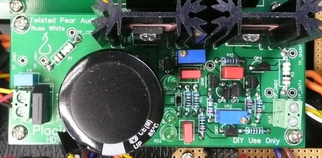
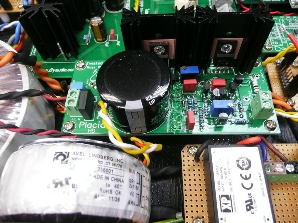
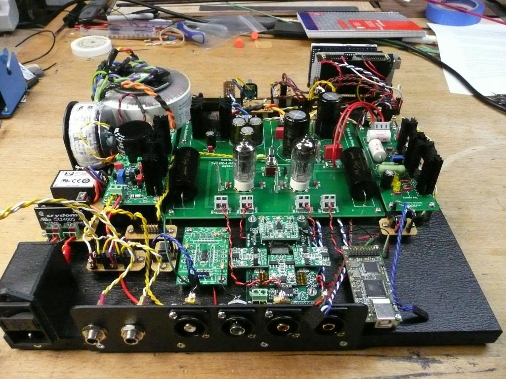
SOLVED I tested the ohm's on the old HD VR1 & 2 and adjusted the new HD to similar values & sure enough had more than the voltage required. It appears if VR1 is not set high enough you'll never get the 5.25V. The testing hasn't gone well so far. I overcame my issue with the power getting to the Placid HD but now I cannot get the required voltage out of the Placid. I set VR1 to 100 ohms & VR2 to 10K You say in the manual the resistance for VR1 & VR2 can be checked across R1 & R2 I'm not sure how that is suppose to work all I get is the resistance of R1 & R2, I'm obviously missing something. My A/C is 248V The A/C coming out of the transformer secondaries is 11.27V The DC between Grnd 1 & Vin is 14V The DC between Grnd 1 & TP CCS is 14V The DC between Grnd 2 & Vout only varies between 4.4V & 4.6V no matter where VR2 is set The DC between Grnd 2 & TP Shunt only varies between 4.4V & 4.6V no matter where VR2 is set. The reference voltage is 3.886V Any thoughts? For what it's worth, the voltage at Grnd 1 & Vin is 12V for my other Placid HD that's in my first DAC and working fine, I'm not sure why they would be any different, same type of transformer etc. Pictures of the new HD below   David Edited by user Monday, March 4, 2013 11:35:48 AM(UTC)
| Reason: Not specified
|
|
|
|
|
|
Rank: Member
Groups: Member
Joined: 5/23/2010(UTC)
Posts: 708
Location: Netherlands
Thanks: 2 times
Was thanked: 48 time(s) in 45 post(s)
|
Originally Posted by: DQ828 
You say in the manual the resistance for VR1 & VR2 can be checked across R1 & R2 I'm not sure how that is suppose to work all I get is the resistance of R1 & R2, I'm obviously missing something.
I think you did miss the fact the manual states you need to measure the voltage across the resistors: "To measure the current being shunted measure the voltage between TP-OUT and TP-SHUNT".
|
|
|
|
|
|
Rank: Member
Groups: Member
Joined: 1/6/2012(UTC)
Posts: 305
Location: Plainfield, IL
Thanks: 11 times
Was thanked: 26 time(s) in 21 post(s)
|
|
|
|
|
|
|
|
Rank: Member
Groups: Member
Joined: 8/17/2010(UTC)
Posts: 368
Location: australia
Thanks: 8 times
Was thanked: 3 time(s) in 3 post(s)
|
It would be really helpful if there was a bit more diligence in the manuals. For instance, when you go to the Documentation page & look for the latest manual for the Placid HD, you don’t find one. I assumed that I was to use the latest Placid manual, and that you haven't bothered to update the manual for the HD version, which is not out of character. Then of course you go to the Placid HD purchasing page & the manual links you to the Placid HD BP manual. A little bit of tidying up on the TP end would help the users greatly I'm sure, in fact in the long run it may even cut down on the forum questions you have to answer.
I'm sure Leon would do a great job of keeping things in order judging by his manual.
|
|
|
|
|
|
Rank: Member
Groups: Member
Joined: 8/17/2010(UTC)
Posts: 368
Location: australia
Thanks: 8 times
Was thanked: 3 time(s) in 3 post(s)
|
Originally Posted by: SCompRacer  I like it :) My problem was I was following the wrong manual. Edited by user Monday, March 4, 2013 10:35:01 PM(UTC)
| Reason: Not specified
|
|
|
|
|
|
Rank: Administration
Groups: Administration, Customer
Joined: 10/24/2006(UTC)
Posts: 3,979
Location: Nashville, TN
Thanks: 25 times
Was thanked: 89 time(s) in 83 post(s)
|
The placid HD is exactly the same as the positive end of the Placid HD-BP. :) Thus they share a manual.
|
|
|
|
|
|
Rank: Member
Groups: Member
Joined: 8/17/2010(UTC)
Posts: 368
Location: australia
Thanks: 8 times
Was thanked: 3 time(s) in 3 post(s)
|
Originally Posted by: Russ White  The placid HD is exactly the same as the positive end of the Placid HD-BP. :) Thus they share a manual. Perhaps in the Document page you could put Placid HD & Placid HD BP Manual, and in the actual document you could change the heading to say the same thing.
|
|
|
|
|
|
Rank: Member
Groups: Member
Joined: 8/17/2010(UTC)
Posts: 368
Location: australia
Thanks: 8 times
Was thanked: 3 time(s) in 3 post(s)
|
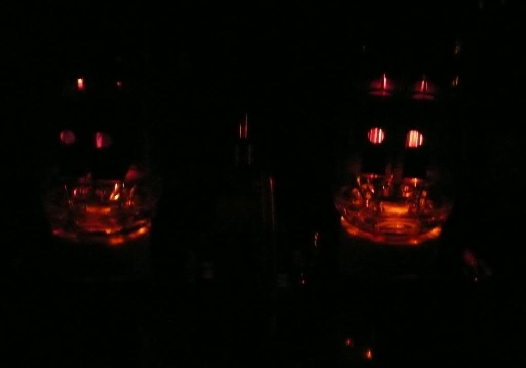
Still no smoke but there is fire  [img]  [/img]  Edited by user Wednesday, March 6, 2013 10:24:23 AM(UTC)
| Reason: Not specified
|
|
|
|
|
|
Rank: Administration
Groups: Administration, Customer
Joined: 10/24/2006(UTC)
Posts: 2,869
Location: Massachusetts, USA
Thanks: 2 times
Was thanked: 141 time(s) in 134 post(s)
|
Originally Posted by: DQ828 
Any thoughts on how I should deal with the the Common Mode Distortion issue?
Use both side of the balanced outputs. By only using +out, you are taking a huge hit in performance. (I realize this is not possible with the output stage you are using, without adding a bal->se stage in between.)
|
|
|
|
|
|
Rank: Member
Groups: Member
Joined: 8/17/2010(UTC)
Posts: 368
Location: australia
Thanks: 8 times
Was thanked: 3 time(s) in 3 post(s)
|
Originally Posted by: Brian Donegan  Originally Posted by: DQ828 
Any thoughts on how I should deal with the the Common Mode Distortion issue?
Use both side of the balanced outputs. By only using +out, you are taking a huge hit in performance. (I realize this is not possible with the output stage you are using, without adding a bal->se stage in between.) Can you recommend a Bal>SE stage?
|
|
|
|
|
|
Rank: Member
Groups: Member
Joined: 5/23/2010(UTC)
Posts: 708
Location: Netherlands
Thanks: 2 times
Was thanked: 48 time(s) in 45 post(s)
|
Take a look at the Ventus (EZ) kits.
|
|
|
|
|
|
Rank: Member
Groups: Member
Joined: 1/19/2011(UTC)
Posts: 332
Location: Oslo, Norway
Thanks: 14 times
Was thanked: 17 time(s) in 17 post(s)
|
What about the IV convertion then? Am I missing something here. Is your connection not directly from the Current output DAC straight into the Tube IV-linestage?
Is it possible to connect the Buffalo directly into the Ventus(ez) with no IV convertion?
|
|
|
|
|
|
Rank: Member
Groups: Member
Joined: 8/17/2010(UTC)
Posts: 368
Location: australia
Thanks: 8 times
Was thanked: 3 time(s) in 3 post(s)
|
Originally Posted by: gwikse  What about the IV convertion then? Am I missing something here. Is your connection not directly from the Current output DAC straight into the Tube IV-linestage?
Is it possible to connect the Buffalo directly into the Ventus(ez) with no IV convertion? My connection is straight from the BIIISE +Out & Grnd, to the Tube-I-Zator Signal In + & Grnd, which goes to the I/V stage and out.. I believe Brian is saying I should ideally be using the BIIISE +, - & Grnd outputs as you would in a balanced output but then convert it to SE before going to the Tube-I-Zator I/V stage. Edited by user Thursday, March 7, 2013 3:19:03 AM(UTC)
| Reason: Not specified
|
|
|
|
|
|
Rank: Administration
Groups: Administration, Customer
Joined: 10/24/2006(UTC)
Posts: 2,869
Location: Massachusetts, USA
Thanks: 2 times
Was thanked: 141 time(s) in 134 post(s)
|
I was/am to mention it at all, since you have your DAC built, and I don't want to be sour. It will probably be just fine the way it is, and I am just nit-picking (I am an engineer after all... "It's what I do").
It's really a problem of using a single-ended I/V stage with a balanced DAC. I'll admit that I am not a fan of the Tube-I-Zator stuff in general, but especially for the Buffalo, since it is not balanced (no common mode cancellation) and has too high of an input impedance to keep the Buffalo from acting as a voltage source.
All that said, people use it and seem to like it, so who am I to call foul. Just enjoy your work... it is a very good build.
|
|
|
|
|
|
Rank: Member
Groups: Member
Joined: 8/17/2010(UTC)
Posts: 368
Location: australia
Thanks: 8 times
Was thanked: 3 time(s) in 3 post(s)
|
Originally Posted by: Brian Donegan  I was/am to mention it at all, since you have your DAC built, and I don't want to be sour. It will probably be just fine the way it is, and I am just nit-picking (I am an engineer after all... "It's what I do").
It's really a problem of using a single-ended I/V stage with a balanced DAC. I'll admit that I am not a fan of the Tube-I-Zator stuff in general, but especially for the Buffalo, since it is not balanced (no common mode cancellation) and has too high of an input impedance to keep the Buffalo from acting as a voltage source.
All that said, people use it and seem to like it, so who am I to call foul. Just enjoy your work... it is a very good build.
No worries, I went into this knowing that it may not be as good as the IVY. At least I will be able to compare & see which one my ears like. I will try & setup a blind switching (if I get around to it) unit like the one I copied to compare my amps and see if there is any instantly noticeable difference. Anyway, I just enjoy the building, maybe even more than the music!!! I'll go and wash my mouth out now.
|
|
|
|
|
|
Rank: Member
Groups: Member
Joined: 8/17/2010(UTC)
Posts: 368
Location: australia
Thanks: 8 times
Was thanked: 3 time(s) in 3 post(s)
|
Originally Posted by: DQ828  Originally Posted by: Brian Donegan 
All that said, people use it and seem to like it.
Of course they do they have a lot of time & money invested  No worries, I went into this knowing that I may not like it as much as the IVY. At least I will be able to compare & see which one my ears like. I will try & setup a blind switching (if I get around to it) unit like the one I copied to compare my amps and see if there is any instantly noticeable difference. Anyway, I just enjoy the building, maybe even more than the music!!! I'll go and wash my mouth out now.
|
|
|
|
|
|
Rank: Member
Groups: Member
Joined: 1/6/2012(UTC)
Posts: 305
Location: Plainfield, IL
Thanks: 11 times
Was thanked: 26 time(s) in 21 post(s)
|
Originally Posted by: DQ828  I will try & setup a blind switching..... That is really difficult to do and some folks tend to tense up when "tested." You seem really grounded. Best just to listen and stay with what you like. The other side of the coin where you can't lie to nobody like you can lie to yourself is we can be totally and brutally honest with ourselves. |
|
|
|
|
|
|
Rank: Member
Groups: Member
Joined: 8/17/2010(UTC)
Posts: 368
Location: australia
Thanks: 8 times
Was thanked: 3 time(s) in 3 post(s)
|
Originally Posted by: SCompRacer  Originally Posted by: DQ828  I will try & setup a blind switching..... That is really difficult to do and some folks tend to tense up when "tested." You seem really grounded. Best just to listen and stay with what you like. The other side of the coin where you can't lie to nobody like you can lie to yourself is we can be totally and brutally honest with ourselves. Yes. With the amps, I found it really hard to tell the difference between them when I was doing the blind switching, although the kids (late teens) could tell. But with extended listening it was obvious to me which was the best. Edited by user Friday, March 8, 2013 11:32:32 PM(UTC)
| Reason: Not specified
|
|
|
|
|
|
Forum Jump
You cannot post new topics in this forum.
You cannot reply to topics in this forum.
You cannot delete your posts in this forum.
You cannot edit your posts in this forum.
You cannot create polls in this forum.
You cannot vote in polls in this forum.