Rank: Member
Groups: Member
Joined: 3/2/2012(UTC)
Posts: 9
Location: USA
|
Originally Posted by: DQ828  Well I'll be damned, I got the modified code to compile  Of course that doesn't mean it will work. Finally had the time to test this - I can confirm that you can use a single pin on the Arduino to switch between SPDIF and I2S on the BIII-SE. If you want to see the code I used, I posted it here: http://buffalodac.wordpr...udio-buffalo-iii-se-dac/
|
|
|
|
|
|
Rank: Member
Groups: Member
Joined: 5/23/2010(UTC)
Posts: 708
Location: Netherlands
Thanks: 2 times
Was thanked: 48 time(s) in 45 post(s)
|
Great to see you've got it working.
|
|
|
|
|
|
Rank: Member
Groups: Member
Joined: 8/17/2010(UTC)
Posts: 368
Location: australia
Thanks: 8 times
Was thanked: 3 time(s) in 3 post(s)
|
In the first instance I have decided to go with Version 5 & will move on to V5a once it is up & working. V5 uses relays for the Source switching & the SPDIF/DSD switching. The Arduino & BIISE are isolated except for the I2C connection, V5a will have an isolator on the I2C. The Amanero will not be isloated in this version but will be in the V5a version. Have made a start on the wiring but things will progress slowly due to time constants, my fancy soldering iron stopped working last night so this morning I dragged out my old iron which came directly from China, what a difference, can't wait for the new one to be fixed. Fortunately it is still under warranty It's a bit disappointing that the new Weller which cost 3 x the Chinese one stop after 11 months of light work & the Chinese clunker is still going. Of course the code is written for V5a, so I'll have to make some minor changes for V5 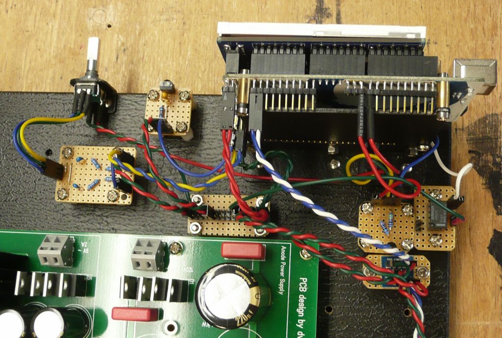 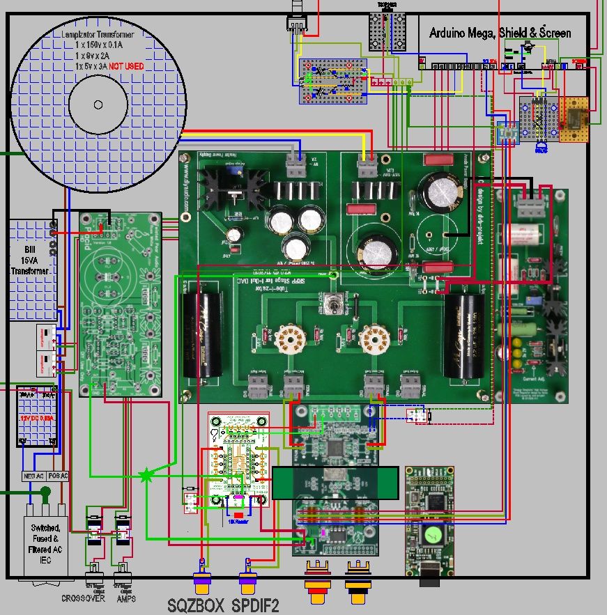
|
|
|
|
|
|
Rank: Member
Groups: Member
Joined: 8/17/2010(UTC)
Posts: 368
Location: australia
Thanks: 8 times
Was thanked: 3 time(s) in 3 post(s)
|
Originally Posted by: chryses  Originally Posted by: DQ828  Well I'll be damned, I got the modified code to compile  Of course that doesn't mean it will work. Finally had the time to test this - I can confirm that you can use a single pin on the Arduino to switch between SPDIF and I2S on the BIII-SE. If you want to see the code I used, I posted it here: http://buffalodac.wordpr...udio-buffalo-iii-se-dac/ Thanks, I think I have that side of the code sorted, time will tell. Of course now I'm going with the relay I'll have to change it 
|
|
|
|
|
|
Rank: Member
Groups: Member
Joined: 8/17/2010(UTC)
Posts: 368
Location: australia
Thanks: 8 times
Was thanked: 3 time(s) in 3 post(s)
|
As I'm doing a direct connection between the BIII SE & the Amanero, should I connect the Grounds as shown in the pic? 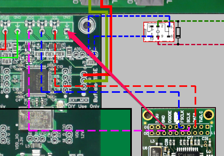
|
|
|
|
|
|
Rank: Member
Groups: Member
Joined: 1/6/2012(UTC)
Posts: 305
Location: Plainfield, IL
Thanks: 11 times
Was thanked: 26 time(s) in 21 post(s)
|
I would and did with mine. I treated it like the OTTO II, Teleporter and Sidecar; GND's are connected between them. Pins 8 and 13-20 are GND on the Amanero. Pin 3 is DATA, pin 4 CLK, pin 5 FSCLK. I used coax and a two row connector, attaching coax GND at 13, 14 and 15 (next to pins 3, 4 and 5). The three coax grounds at the Sidecar/OTTO end are all tied together and connect to GND. I sourced the coax from some old S Video cables. Some S Video cables just use wire with a braided wire shield. If you use twisted wire you just need one GND. 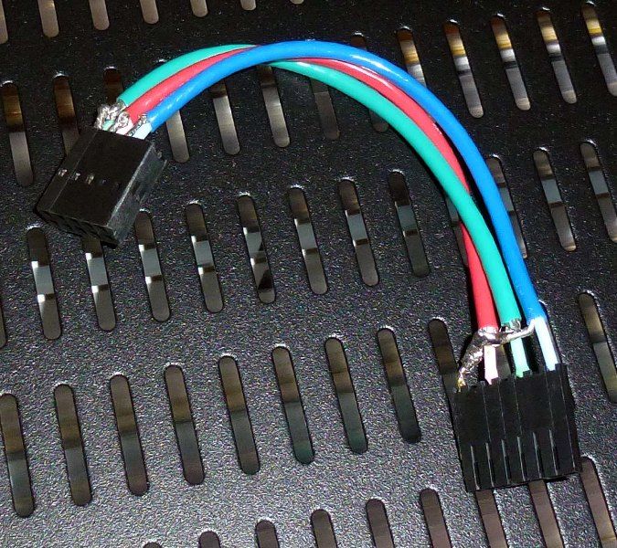 Edited by user Sunday, February 17, 2013 5:33:11 PM(UTC)
| Reason: Not specified |
|
|
|
|
|
|
Rank: Member
Groups: Member
Joined: 8/17/2010(UTC)
Posts: 368
Location: australia
Thanks: 8 times
Was thanked: 3 time(s) in 3 post(s)
|
I remember reading in a post somewhere, that somebody had implemented a system where the audio system would turn off if a signal was not received after a period of time. Does anyone know who posted that or how it would be done? Edited by user Wednesday, February 20, 2013 9:40:41 AM(UTC)
| Reason: Not specified
|
|
|
|
|
|
Rank: Member
Groups: Member
Joined: 1/19/2011(UTC)
Posts: 332
Location: Oslo, Norway
Thanks: 14 times
Was thanked: 17 time(s) in 17 post(s)
|
|
 1 user thanked gwikse for this useful post.
|
|
|
|
Rank: Member
Groups: Member
Joined: 8/17/2010(UTC)
Posts: 368
Location: australia
Thanks: 8 times
Was thanked: 3 time(s) in 3 post(s)
|
Originally Posted by: gwikse  http://www.ce-designs.net/index.php/shop/single-pcbs/signal-detection-auto-on-off-unit
And some code on the arduino if you have a relay that cut the Power to the IV stage. Thanks I'm actually looking for something I can put in the Sub I'm building for the son, it'll never get turned off otherwise :)
|
|
|
|
|
|
Rank: Member
Groups: Member
Joined: 2/1/2012(UTC)
Posts: 332
Location: The Netherlands
Thanks: 4 times
Was thanked: 18 time(s) in 18 post(s)
|
you can use it in any device that has an analog audio input. |
|
|
|
|
|
|
Rank: Member
Groups: Member
Joined: 8/17/2010(UTC)
Posts: 368
Location: australia
Thanks: 8 times
Was thanked: 3 time(s) in 3 post(s)
|
Originally Posted by: Corpius  you can use it in any device that has an analog audio input. I tried to post a question on your site but I don't think it worked. I assume I will need a 12vDC supply permanently powered to run the device? How much current will the PSU need to supply to run the device?
|
|
|
|
|
|
Rank: Member
Groups: Member
Joined: 2/1/2012(UTC)
Posts: 332
Location: The Netherlands
Thanks: 4 times
Was thanked: 18 time(s) in 18 post(s)
|
Originally Posted by: DQ828  Originally Posted by: Corpius  you can use it in any device that has an analog audio input. I tried to post a question on your site but I don't think it worked. I assume I will need a 12vDC supply permanently powered to run the device? How much current will the PSU need to supply to run the device? yes it must be permanent powered. 12 to 15v can be used, but 12v relays are most commonly available. So the advised voltage is 12v. I have not measured the current the circuit takes, but I can assure you that it is very little. Do use a descent transformer because it will be on permanent! Look here for more info: http://sound.westhost.com/project38.htm |
|
|
|
|
|
|
Rank: Member
Groups: Member
Joined: 8/17/2010(UTC)
Posts: 368
Location: australia
Thanks: 8 times
Was thanked: 3 time(s) in 3 post(s)
|
|
|
|
|
|
|
Rank: Member
Groups: Member
Joined: 8/17/2010(UTC)
Posts: 368
Location: australia
Thanks: 8 times
Was thanked: 3 time(s) in 3 post(s)
|
Getting closer all the time. The first TP/Arduino DAC that I build sort of evolved over time, where this one is straight to the end game, well almost. What are the chances of it all working first go,  Slim I'd imagine. 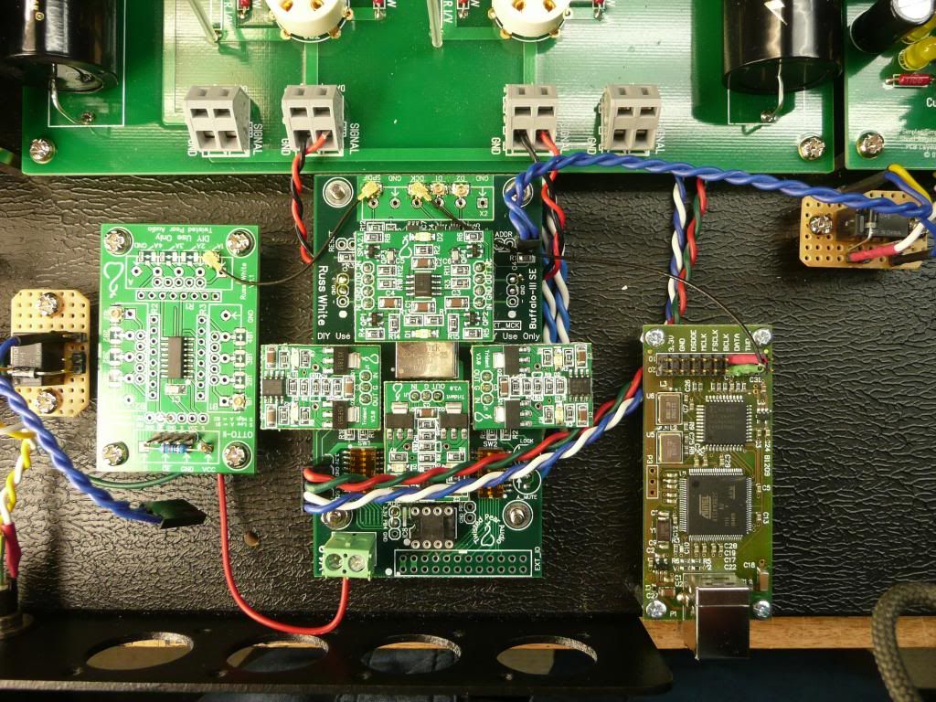 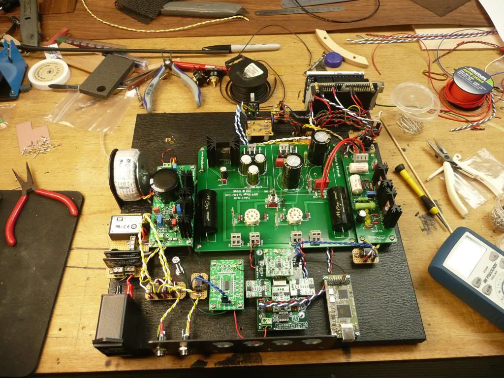
|
|
|
|
|
|
Rank: Administration
Groups: Administration, Customer
Joined: 10/24/2006(UTC)
Posts: 2,869
Location: Massachusetts, USA
Thanks: 2 times
Was thanked: 141 time(s) in 134 post(s)
|
How are you dealing with common-mode distortion?
|
|
|
|
|
|
Rank: Member
Groups: Member
Joined: 8/17/2010(UTC)
Posts: 368
Location: australia
Thanks: 8 times
Was thanked: 3 time(s) in 3 post(s)
|
The common mode what!!
All suggestions are more than welcome, I am ignorant of such things.
|
|
|
|
|
|
Rank: Member
Groups: Member
Joined: 8/17/2010(UTC)
Posts: 368
Location: australia
Thanks: 8 times
Was thanked: 3 time(s) in 3 post(s)
|
I'm seriously over soldering, not much to do now, connect the larger transformer, one more SPDIF input and the Mute & Lock LED, then test everything before I fire it up. Is there any issue with me using a RED LED for the Mute, I remember reading somewhere that the different colour LED's used different amounts of current. Is the Mute just to show when you don't have LOCK or is there a way to actually mute the DAC mid music? 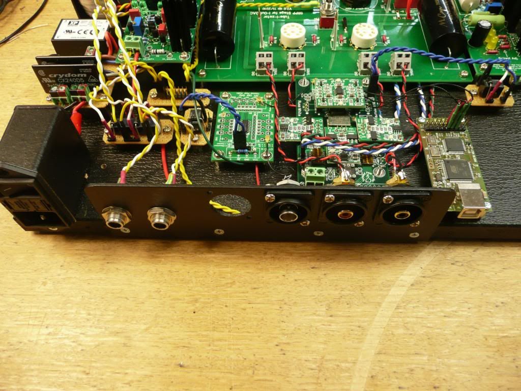 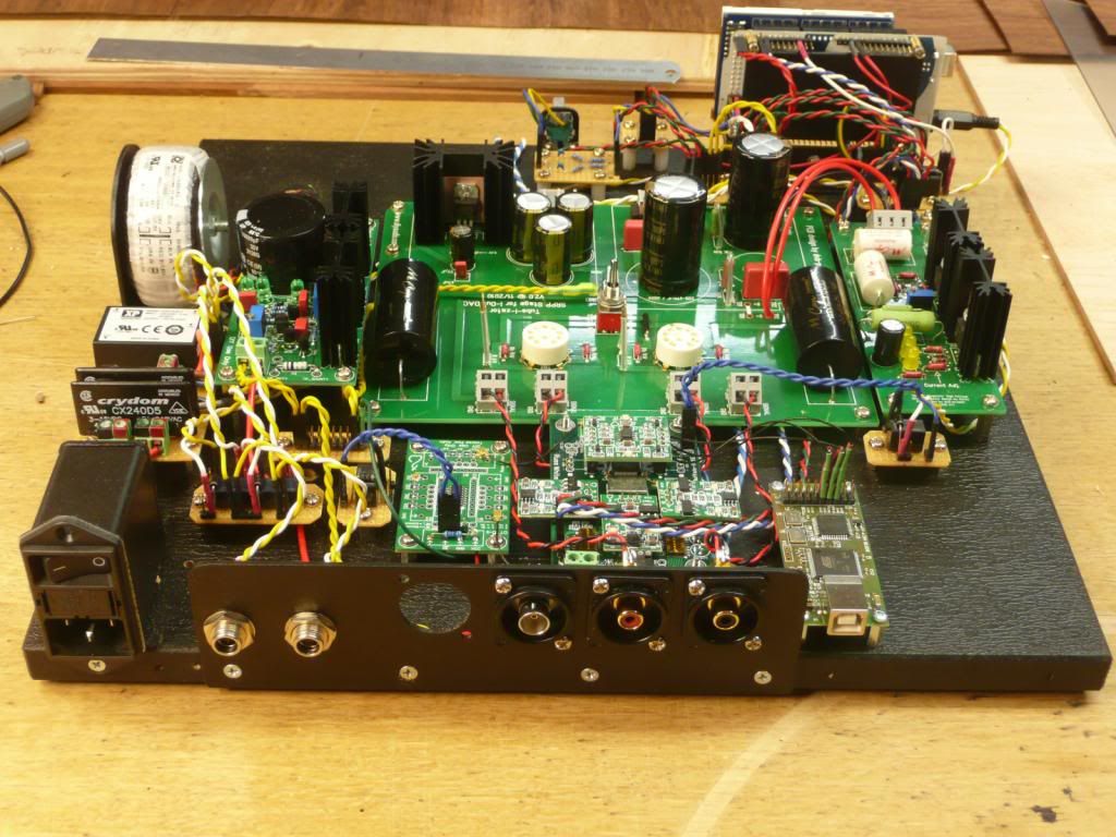 Edited by user Sunday, March 3, 2013 7:35:19 AM(UTC)
| Reason: Not specified
|
|
|
|
|
|
Rank: Member
Groups: Member
Joined: 8/17/2010(UTC)
Posts: 368
Location: australia
Thanks: 8 times
Was thanked: 3 time(s) in 3 post(s)
|
|
|
|
|
|
|
Rank: Member
Groups: Member
Joined: 2/1/2012(UTC)
Posts: 332
Location: The Netherlands
Thanks: 4 times
Was thanked: 18 time(s) in 18 post(s)
|
Originally Posted by: DQ828  I'm seriously over soldering, not much to do now, connect the larger transformer, one more SPDIF input and the Mute & Lock LED, then test everything before I fire it up. Is there any issue with me using a RED LED for the Mute, I remember reading somewhere that the different colour LED's used different amounts of current. Is the Mute just to show when you don't have LOCK or is there a way to actually mute the DAC mid music?   I used red LED's at first, but now my build has no LED's at all. The display is also indicating if the DAC is locked to the signal. Only dropouts that happent for a split second are not likely to be picked up by the arduino. The mute LED lights up when you mute your DAC using the arduino and also between the songs when automute is enabled. It has nothing to do with the lock state, but when automute is enabled it will stay muted while there is no lock :) |
|
|
|
|
|
|
Rank: Administration
Groups: Administration, Customer
Joined: 10/24/2006(UTC)
Posts: 2,869
Location: Massachusetts, USA
Thanks: 2 times
Was thanked: 141 time(s) in 134 post(s)
|
Quote:Is there any issue with me using a RED LED for the Mute, I remember reading somewhere that the different colour LED's used different amounts of current. The only issue would be using LEDs that draw lots of current, like blue or high-output white LEDs. Standard Red, Orange, Yellow, Green etc are fine.
|
|
|
|
|
|
Forum Jump
You cannot post new topics in this forum.
You cannot reply to topics in this forum.
You cannot delete your posts in this forum.
You cannot edit your posts in this forum.
You cannot create polls in this forum.
You cannot vote in polls in this forum.