Rank: Member
Groups: Member
Joined: 11/8/2011(UTC)
Posts: 11
Location: FRANCE
Was thanked: 1 time(s) in 1 post(s)
|
Hello everyone, I'm stuck with the Placid HD BIPOLAR  It only give me 5V out whatever I do with VR2 It only give me 5V out whatever I do with VR2... 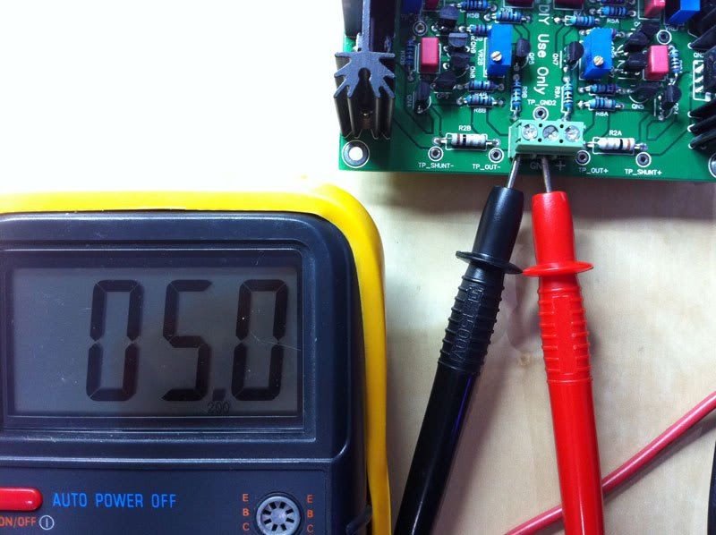 I surely made a mistake but can't find what & where. So let's start with the begining : Power Supply . I have this R-core transformer (30VA with 2 secondary at 15V) and here is how I wire this : 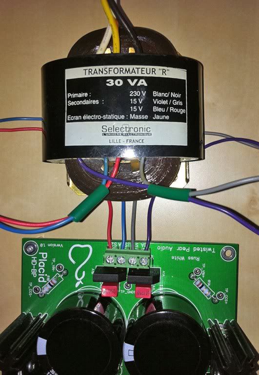 then the measurements values:     
Can anyone help me ?Thanks Edited by user Wednesday, November 30, 2011 7:05:12 AM(UTC)
| Reason: Not specified
|
 1 user thanked patrocle for this useful post.
|
|
|
|
Rank: Administration
Groups: Administration, Customer
Joined: 10/24/2006(UTC)
Posts: 3,979
Location: Nashville, TN
Thanks: 25 times
Was thanked: 89 time(s) in 83 post(s)
|
Hmmm. That is strange indeed. :) This would tend to indicate that the pot is stuck at the highest (or close) resistance. It is possible to damage the pot by over-adjusting it (it can distort the wiper). You have a couple of options. Make sure VR2A is well soldered. Give VR2A a few flicks with your finger. Try to adjust it again. If you find you still can't adjust it then it may be time to replace it, or even better I would just not use VR2 to set your voltage by removing them and use fixed resistors there instead. If you are shooting for +/-~15V you could use ~750R instead of the pots. If you are shooting for +/-~12V try ~931R Cheers! Russ Edited by user Tuesday, November 29, 2011 11:59:35 AM(UTC)
| Reason: Not specified
|
|
|
|
|
|
Rank: Administration
Groups: Administration, Customer
Joined: 10/24/2006(UTC)
Posts: 3,979
Location: Nashville, TN
Thanks: 25 times
Was thanked: 89 time(s) in 83 post(s)
|
It looks like based on you rectified voltage of about 16V your not going to be able to get 15V output I would shoot for 12-13V depending on what you are powering.
|
|
|
|
|
|
Rank: Administration
Groups: Administration, Customer
Joined: 10/24/2006(UTC)
Posts: 3,979
Location: Nashville, TN
Thanks: 25 times
Was thanked: 89 time(s) in 83 post(s)
|
Good pictures BTW. Very helpful.
|
|
|
|
|
|
Rank: Member
Groups: Member
Joined: 11/8/2011(UTC)
Posts: 11
Location: FRANCE
Was thanked: 1 time(s) in 1 post(s)
|
Thank you very much for your answers ! This Placid BP is for powering an IVY III stage. I re-soldered the VR2, nothing changed, and did I mentioned that the problem is the same on the other rail? Anyway, I've ordered 750R resistors that I should receive tomorrow. In the meantime, I've made some new pictures, maybe your fresh and expert look will see something obvious that I don't !   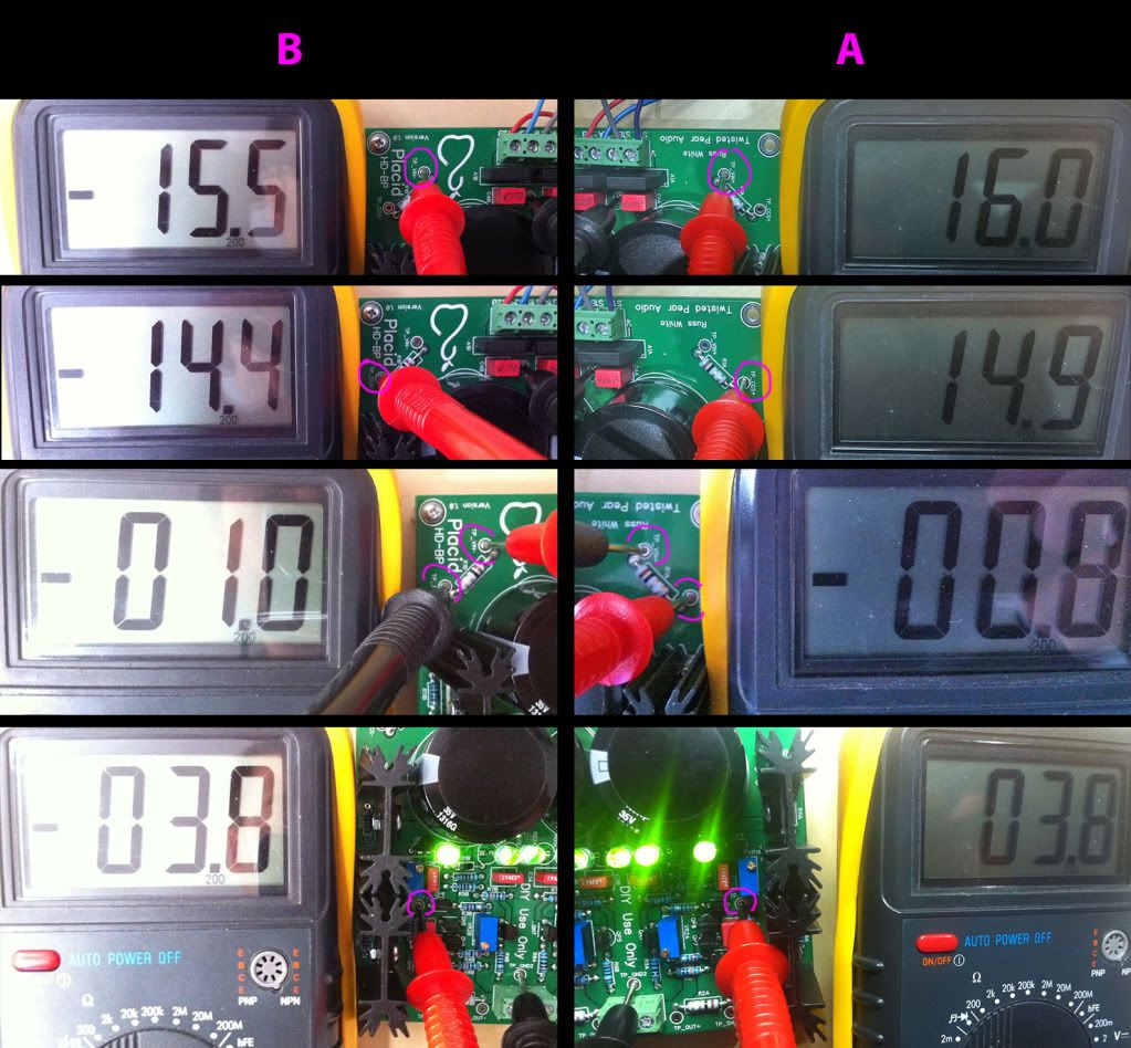 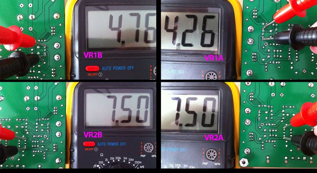 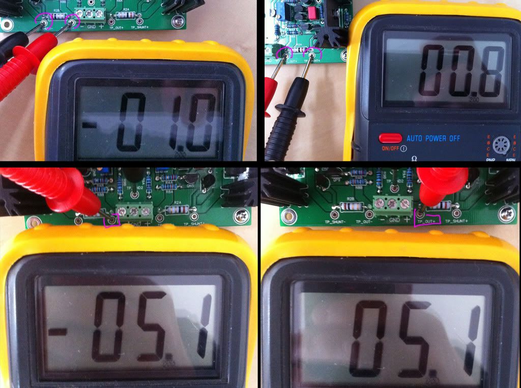 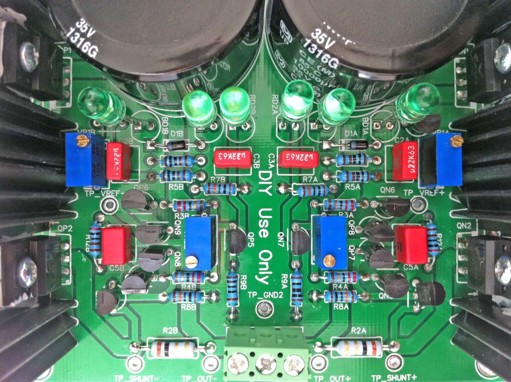 thanks again ! Edited by user Wednesday, November 30, 2011 5:59:45 AM(UTC)
| Reason: Not specified
|
|
|
|
|
|
Rank: Member
Groups: Member
Joined: 11/8/2011(UTC)
Posts: 11
Location: FRANCE
Was thanked: 1 time(s) in 1 post(s)
|
Another thing : I was looking at the Schema and figure out that C4 have a 220nF value, but in the kit I've received, C4 components have a value of 0.1uF (received 2 pairs by the way :) Might this be a problem ?  thank you ! Edited by user Wednesday, November 30, 2011 5:51:23 AM(UTC)
| Reason: Not specified
|
|
|
|
|
|
Rank: Administration
Groups: Administration, Customer
Joined: 10/24/2006(UTC)
Posts: 2,869
Location: Massachusetts, USA
Thanks: 2 times
Was thanked: 141 time(s) in 134 post(s)
|
Just a problem in the schematic :). Either value is fine.
|
|
|
|
|
|
Rank: Administration
Groups: Administration, Customer
Joined: 10/24/2006(UTC)
Posts: 3,979
Location: Nashville, TN
Thanks: 25 times
Was thanked: 89 time(s) in 83 post(s)
|
Not so much a problem. But clearly a difference. As Brian said either value is perfectly fine there. :) The schematic is how the cct was designed, but for some parts a range of values is just fine. For that spot .1uf is just as good as .22uf. :) We will edit the schematic to reflect what is actually supplied though, for consistency sake. :) Edited by user Wednesday, November 30, 2011 6:12:50 AM(UTC)
| Reason: Not specified
|
|
|
|
|
|
Rank: Administration
Groups: Administration, Customer
Joined: 10/24/2006(UTC)
Posts: 3,979
Location: Nashville, TN
Thanks: 25 times
Was thanked: 89 time(s) in 83 post(s)
|
You can check if the VR2 pots are working correctly by measuring the resistance across them with the power off and adjusting. If you are getting the full range of adjustment then the problem is elsewhere.
I would double check that all of the transistors are the correct part in the correct spot. :)
Cheers!
Russ
|
|
|
|
|
|
Rank: Member
Groups: Member
Joined: 11/8/2011(UTC)
Posts: 11
Location: FRANCE
Was thanked: 1 time(s) in 1 post(s)
|
OK thanks,
as you can see on previous pictures, I've adjusted VR2 to be at 750R ( power off) and have no problem of getting full range of adjustment.
I've already double check each transistor, I'll doing it again and take pictures.
Thanks again for your help
|
|
|
|
|
|
Rank: Administration
Groups: Administration, Customer
Joined: 10/24/2006(UTC)
Posts: 3,979
Location: Nashville, TN
Thanks: 25 times
Was thanked: 89 time(s) in 83 post(s)
|
Hmm what I saw there looked like a voltage reading of 7.50V Not a resistance reading of 750 ohms.
|
|
|
|
|
|
Rank: Member
Groups: Member
Joined: 11/8/2011(UTC)
Posts: 11
Location: FRANCE
Was thanked: 1 time(s) in 1 post(s)
|
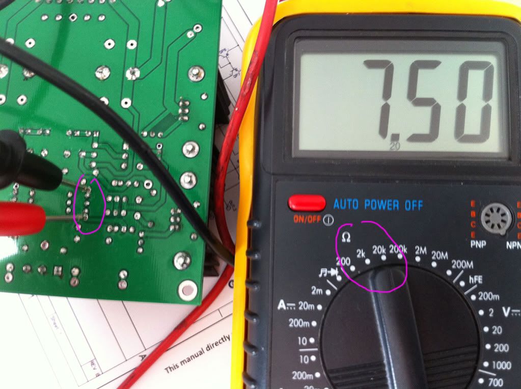 :)
|
|
|
|
|
|
Rank: Administration
Groups: Administration, Customer
Joined: 10/24/2006(UTC)
Posts: 3,979
Location: Nashville, TN
Thanks: 25 times
Was thanked: 89 time(s) in 83 post(s)
|
Ah I see. Very good thanks! Just double checking.
The next thing to do will be to confirm that there are no incorrect part values in any spots. Compare what is installed to the schematic.
|
|
|
|
|
|
Rank: Administration
Groups: Administration, Customer
Joined: 10/24/2006(UTC)
Posts: 3,979
Location: Nashville, TN
Thanks: 25 times
Was thanked: 89 time(s) in 83 post(s)
|
Actually wouldn't that be a reading of 7.5K?
|
|
|
|
|
|
Rank: Member
Groups: Member
Joined: 11/8/2011(UTC)
Posts: 11
Location: FRANCE
Was thanked: 1 time(s) in 1 post(s)
|
|
|
|
|
|
|
Rank: Administration
Groups: Administration, Customer
Joined: 10/24/2006(UTC)
Posts: 3,979
Location: Nashville, TN
Thanks: 25 times
Was thanked: 89 time(s) in 83 post(s)
|
All is well that ends well. :)
I wouldn't have been able to help if you had not provided good information. This thread should be a lesson to others on how to get help on trouble shooting issues. :)
BTW based on your rectified voltage of around 15-16V I would shoot for 12-13V not 15. You will not have enough headroom for good regulation if you try to go higher than 14V.
Cheers!
Russ
|
|
|
|
|
|
Rank: Member
Groups: Member
Joined: 11/8/2011(UTC)
Posts: 11
Location: FRANCE
Was thanked: 1 time(s) in 1 post(s)
|
thanks for the compliment :) And Except I'm now around 25V with the right configuration onboard, So I think I can go for 15vout ? 
|
|
|
|
|
|
Rank: Administration
Groups: Administration, Customer
Joined: 10/24/2006(UTC)
Posts: 3,979
Location: Nashville, TN
Thanks: 25 times
Was thanked: 89 time(s) in 83 post(s)
|
Absolutely. You have more than enough headroom now. :) 2-3V headroom is all that is really needed for excellent regulation. Cheers! Russ Edited by user Wednesday, November 30, 2011 8:00:31 AM(UTC)
| Reason: Not specified
|
|
|
|
|
|
Rank: Member
Groups: Member
Joined: 11/8/2011(UTC)
Posts: 11
Location: FRANCE
Was thanked: 1 time(s) in 1 post(s)
|
GREAT ! thank you
Last question of the day (I hope, doesn't want to monopolize your time):
I have 3 IVY III stages, do I need 3 PLACID BP or can I use just this one set at 150mA*3 = 450mA ?
|
|
|
|
|
|
Rank: Member
Groups: Member
Joined: 5/23/2010(UTC)
Posts: 708
Location: Netherlands
Thanks: 2 times
Was thanked: 48 time(s) in 45 post(s)
|
From the pictures it looks like you have a HD version, it should be ok to power up to 4 IVY3's according to Russ.
|
|
|
|
|
|
Forum Jump
You cannot post new topics in this forum.
You cannot reply to topics in this forum.
You cannot delete your posts in this forum.
You cannot edit your posts in this forum.
You cannot create polls in this forum.
You cannot vote in polls in this forum.