Welcome Guest! To enable all features please Login or Register.

Notification

Icon
Error

Login


Options
View
Go to last post Go to first unread
Hercules  
#1 Posted : Thursday, August 12, 2010 8:18:46 AM(UTC)
Hercules

Rank: Advanced Member

Groups: Member
Joined: 4/16/2009(UTC)
Posts: 56
Location: Hong Kong

Dear All:

I just installed Volumite yesterday, before I'm using BII with Toslink module, sharing one Single Placid Power Supply at 5.5V, 350mA, powered by 15VA 9VAC transformer from TPA. After adding the Volumite, my buffalo PCB started to behave abnormally, LED D1 on the AVCC start flashing and became very dim (still have very weak light emitted), failed to lock incoming SPDIF, then all LED light off on the BII and AVCC PCB, I thought my Buffalo already GONE at that moment, the voltage measured at VD is only 1.5V compared with original 5.5V. Then I disconnect the Toslink and Volumite, just powered the BII and AVCC alone, still no miracles happening to me. When disconnect the Placid with BII PCB, the VD back to 5.5V.

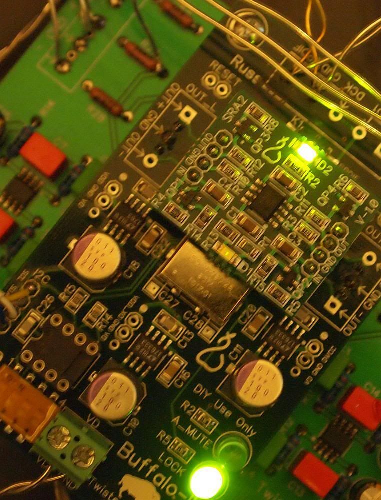
After I leave it off for a day, and try to troubleshoot again today, the BII A_Mute and D2 lighted up, but still can't lock anything incoming. Then I shorted the reset header, BII started to lock and singing again, then I put back the volumite, it's working normally, but the D1 still found very dim.

Then I made measurement of all supply rail on the BII and AVCC module, the measurement as follwing:

VD measured at VD header, BII PCB and AVCC board: 5.5V
VDD: 1.2V
VDD_XO: 3.3V
AVCC: Left side 4.6V, Right side 3.5V
DVCC: 3.3V

Voltage across D1 of AVCC board: 2.0V - very dim
Voltage across D2 of AVCC board: 1.5V - light up

Russ suggested my to increase the current of Placid, so I increase to 380mA now (tried 450mA, D1 still very dim), I'm not sure is it still safe to use the Buffalo now, anyone can advise me what can I do?? Thanks
UserPostedImage

Edited by user Thursday, August 12, 2010 8:40:55 AM(UTC)  | Reason: Not specified

Russ White  
#2 Posted : Thursday, August 12, 2010 8:24:53 AM(UTC)
Russ White

Rank: Administration

Groups: Administration, Customer
Joined: 10/24/2006(UTC)
Posts: 3,979
Location: Nashville, TN

Thanks: 25 times
Was thanked: 89 time(s) in 83 post(s)
I would adjust the Placid so that it is shunting only about 50ma.

The output from both sides of the AVCC module should be identical.

While working on the DAC you may have damaged the AVCC module, you may simply need a new one.
Hercules  
#3 Posted : Thursday, August 12, 2010 8:45:54 AM(UTC)
Hercules

Rank: Advanced Member

Groups: Member
Joined: 4/16/2009(UTC)
Posts: 56
Location: Hong Kong

Russ White wrote:
I would adjust the Placid so that it is shunting only about 50ma.

The output from both sides of the AVCC module should be identical.

While working on the DAC you may have damaged the AVCC module, you may simply need a new one.


How can I get the new one??? and I tried to lower current supply to 320mA, shunted current around 50mA now.

Thanks again Russ!

Edited by user Thursday, August 12, 2010 11:20:15 AM(UTC)  | Reason: Not specified

Hercules  
#4 Posted : Friday, August 13, 2010 12:28:02 AM(UTC)
Hercules

Rank: Advanced Member

Groups: Member
Joined: 4/16/2009(UTC)
Posts: 56
Location: Hong Kong

Hi Russ and Brian:

Can I try to replace the opamp myself with OPA2134 or LM4562 to see can I fixed the problem??? and how can I get replacement of the faulty AVCC board?

Russ White  
#5 Posted : Friday, August 13, 2010 3:59:43 AM(UTC)
Russ White

Rank: Administration

Groups: Administration, Customer
Joined: 10/24/2006(UTC)
Posts: 3,979
Location: Nashville, TN

Thanks: 25 times
Was thanked: 89 time(s) in 83 post(s)
The op amp has to be a rail to rail type.

What is the voltage across R6 and R8?
Hercules  
#6 Posted : Friday, August 13, 2010 8:03:21 AM(UTC)
Hercules

Rank: Advanced Member

Groups: Member
Joined: 4/16/2009(UTC)
Posts: 56
Location: Hong Kong

Hi Russ:

R8 is 0.078V, R6 is 0.033V
Russ White  
#7 Posted : Friday, August 13, 2010 2:44:19 PM(UTC)
Russ White

Rank: Administration

Groups: Administration, Customer
Joined: 10/24/2006(UTC)
Posts: 3,979
Location: Nashville, TN

Thanks: 25 times
Was thanked: 89 time(s) in 83 post(s)
Contact Brian if he has not contacted you already. He can get you a replacement.

Cheers!
Russ
Hercules  
#8 Posted : Friday, August 13, 2010 3:11:55 PM(UTC)
Hercules

Rank: Advanced Member

Groups: Member
Joined: 4/16/2009(UTC)
Posts: 56
Location: Hong Kong

Thanks Russ and Brian, Brian is going to send me the replacement AVCC!
Hercules  
#9 Posted : Tuesday, August 24, 2010 3:30:01 AM(UTC)
Hercules

Rank: Advanced Member

Groups: Member
Joined: 4/16/2009(UTC)
Posts: 56
Location: Hong Kong

Thanks Brian and Russ, I received the AVCC board replacement and fixed the problems, but I reviewed some of the photo before I added volumite, the D1 already went dimmed, maybe the AVCC board I got was defective from Day 1.

Taken on 31 July, 2010, both D1 and D2 on the AVCC board were normal

UserPostedImage

Taken on 1 Aug, 2010, D1 of the AVCC already dimmed, but it still sings normally so I didn't notice the problem

UserPostedImage

and the problem getting worse after the additional volumite added stress to Placid supply, and affected the whole digital board which failed to lock incoming SPDIF.


pelliott123  
#10 Posted : Tuesday, August 24, 2010 5:13:09 AM(UTC)
pelliott123

Rank: Member

Groups: Member
Joined: 8/6/2008(UTC)
Posts: 128
Location: Baltimore, MD USA

I know this is off topic and your concerns is to only get things fixed but I have to ask since you are using an IVY for audio out what is the pencil tube board doing. It looks like you are converting the balanced out form the IVY to SE or what. where is the board from any info would be appreciated. Hope you fix the problem.
Hercules  
#11 Posted : Tuesday, August 24, 2010 9:20:21 AM(UTC)
Hercules

Rank: Advanced Member

Groups: Member
Joined: 4/16/2009(UTC)
Posts: 56
Location: Hong Kong

pelliott123 wrote:
I know this is off topic and your concerns is to only get things fixed but I have to ask since you are using an IVY for audio out what is the pencil tube board doing. It looks like you are converting the balanced out form the IVY to SE or what. where is the board from any info would be appreciated. Hope you fix the problem.


It's called tubefilter made by Hong Kong designer, but he is not longer in this business, this tubefilter can be use in SE or BAL mode, and using pencil Raytheon 5703 for ultra longlife at 24~28V dc, same tube as the MF Tri-Visia series.

[img]http://ep.yimg.com/ca/I/triodeel_2121_56351852[/img]

http://www.diyhifisupply.com/node/408

This one maybe interesting to you, using 6DJ8 based tube, you can do tube-rolling as you like. one module required for SE, two for Balanced.
pelliott123  
#12 Posted : Wednesday, August 25, 2010 5:16:47 AM(UTC)
pelliott123

Rank: Member

Groups: Member
Joined: 8/6/2008(UTC)
Posts: 128
Location: Baltimore, MD USA

I see that, thanks for the suggestion
One other question?
Why are you going from the IVY to the tube circuit instead of going directly from the Buff to the tube circuit?
Hercules  
#13 Posted : Wednesday, August 25, 2010 8:16:16 AM(UTC)
Hercules

Rank: Advanced Member

Groups: Member
Joined: 4/16/2009(UTC)
Posts: 56
Location: Hong Kong

pelliott123 wrote:
I see that, thanks for the suggestion
One other question?
Why are you going from the IVY to the tube circuit instead of going directly from the Buff to the tube circuit?


It's tube output buffer only, not a tube I/V stage.
Brian Donegan  
#14 Posted : Wednesday, August 25, 2010 8:44:47 AM(UTC)
Brian Donegan

Rank: Administration

Groups: Administration, Customer
Joined: 10/24/2006(UTC)
Posts: 2,868
Location: Massachusetts, USA

Thanks: 2 times
Was thanked: 141 time(s) in 134 post(s)
I am curious as to why you need a buffer at all, since the IVY can output so much current as is.

Edited by user Wednesday, August 25, 2010 8:45:21 AM(UTC)  | Reason: Not specified

Hercules  
#15 Posted : Wednesday, August 25, 2010 7:05:53 PM(UTC)
Hercules

Rank: Advanced Member

Groups: Member
Joined: 4/16/2009(UTC)
Posts: 56
Location: Hong Kong

Brian Donegan wrote:
I am curious as to why you need a buffer at all, since the IVY can output so much current as is.


just add more tube sounding only!
Rss Feed  Atom Feed
Users browsing this topic
GuestUser (8)
Forum Jump  
You cannot post new topics in this forum.
You cannot reply to topics in this forum.
You cannot delete your posts in this forum.
You cannot edit your posts in this forum.
You cannot create polls in this forum.
You cannot vote in polls in this forum.