Rank: Member
Groups: Member
Joined: 11/9/2007(UTC)
Posts: 453
Location: usa
|
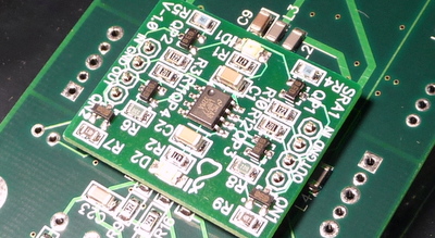
I suppose the Shunt regulator is the same on both sides so that it can be installed back to back on the back side of Buffalo II like this?: 
|
|
|
|
|
|
Rank: Administration
Groups: Administration, Customer
Joined: 10/24/2006(UTC)
Posts: 3,979
Location: Nashville, TN
Thanks: 25 times
Was thanked: 89 time(s) in 83 post(s)
|
Just observe that the pin names on the DAC match up to the correct pin names on the regulator. Both halves of the AVCC cct work identically. Out -> AVCC Gnd -> Gnd IN -> VD No-MARK -> DVCC Notice that while you use a 4 pin header that DVCC is not actually used by this regulator. Your picture has the AVCC module oriented correctly. Edited by user Sunday, March 21, 2010 9:47:56 AM(UTC)
| Reason: Not specified
|
|
|
|
|
|
Rank: Member
Groups: Member
Joined: 11/9/2007(UTC)
Posts: 453
Location: usa
|
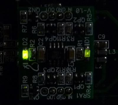
Russ (and Brian), Thanks. Installed the shunt on the back side. Powered the DAC with 5.0V Measured the voltage of the shunt, one side is 3.523 v the other side 3.516v One of the LEDs of the shut is brighter than the other Like this:  I suppose this is perfectly normal PS: the built quality of Buffalo II is very very good... Edited by user Sunday, March 21, 2010 5:24:09 PM(UTC)
| Reason: Not specified
|
|
|
|
|
|
Rank: Administration
Groups: Administration, Customer
Joined: 10/24/2006(UTC)
Posts: 3,979
Location: Nashville, TN
Thanks: 25 times
Was thanked: 89 time(s) in 83 post(s)
|
That's normal, but I would use 5.5V as stated in the manual.
|
|
|
|
|
|
Rank: Member
Groups: Member
Joined: 11/9/2007(UTC)
Posts: 453
Location: usa
|
OK.
Powered with 5.5V
AVCC: 3.556 and 3.554
Both LEDs are more uniform in brightness
Also, the GND plane must be very substantial as I couldn't solder the GND pin with a 25W iron. Had to use the 40W iron.
|
|
|
|
|
|
Rank: Administration
Groups: Administration, Customer
Joined: 10/24/2006(UTC)
Posts: 3,979
Location: Nashville, TN
Thanks: 25 times
Was thanked: 89 time(s) in 83 post(s)
|
Yes the GND plane is pretty much a solid sheet of copper :) but there are thermals, so soldering should be OK.
|
|
|
|
|
|
Rank: Member
Groups: Member
Joined: 11/9/2007(UTC)
Posts: 453
Location: usa
|
 Didn't want to cover up the ESS chip :-) and this way it is a bit lower profile.
|
|
|
|
|
|
Rank: Administration
Groups: Administration, Customer
Joined: 10/24/2006(UTC)
Posts: 3,979
Location: Nashville, TN
Thanks: 25 times
Was thanked: 89 time(s) in 83 post(s)
|
Sure, perfectly reasonable. :) Should work great either way. , just watch clearances if you use the IVY-III.
|
|
|
|
|
|
Rank: Member
Groups: Member
Joined: 7/22/2009(UTC)
Posts: 11
Location: Brisbane
|
yeah I considered doing something like that too, considering the final home for the b32v2 is going to be a portable case, but I checked and when installed the shunt sits at about 2mm higher than the height of the oscons anyway, so I deemed it not worth it. I guess you still skip the pin header connection and 5mm length, but I doubt its meaningful. looks cool though. I wanted the ability to 'unplug' the shunt rather than desoldering it if I find (or one is released) a higher performance reg for each of the positions Edited by user Tuesday, March 23, 2010 6:57:17 AM(UTC)
| Reason: Not specified
|
|
|
|
|
|
Forum Jump
You cannot post new topics in this forum.
You cannot reply to topics in this forum.
You cannot delete your posts in this forum.
You cannot edit your posts in this forum.
You cannot create polls in this forum.
You cannot vote in polls in this forum.