Rank: Member
Groups: Member
Joined: 9/13/2009(UTC)
Posts: 10
Location: Ann Arbor
|
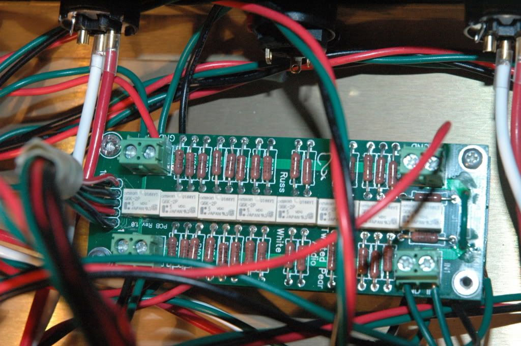
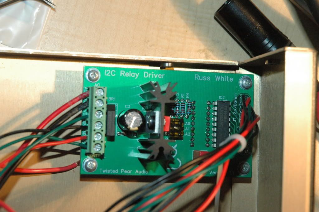
Hi, I'm having problems with a joshua tree. I am powering the relay driver with a secondary of a 9+9V toroid. The wiring between the boards is my own design. I have placed the relay driver and toroid inside my power supply case, the volumite controller and joshua tree relays are in the amplfier board box. These are wired to a DVI headers and cables between the two boxes. pin 1 on the JT2.0 side of the relay driver is wired to pin 1 on the joshua tree board, etc. I've already performed a connectivity check between the two boards. The Volumite controller voltage reads 3.0V between the VDD and ground. Are there any other voltages that I can check to help troubleshoot this?   Thanks. Eugene
|
|
|
|
|
|
Rank: Administration
Groups: Administration, Customer
Joined: 10/24/2006(UTC)
Posts: 2,869
Location: Massachusetts, USA
Thanks: 2 times
Was thanked: 141 time(s) in 134 post(s)
|
What is the problem? I assume you are not getting any response from the relays?
Are the three switches on the relay driver set to off?
|
|
|
|
|
|
Rank: Member
Groups: Member
Joined: 9/13/2009(UTC)
Posts: 10
Location: Ann Arbor
|
Yup,
I'm not getting a response and the three switches are set to off.
I'm assuming:
1. SDA on the relay driver goes to SDA on the volumite
2. SCL on the relay driver goes to SCL on the volumite
Thanks.
eugene
|
|
|
|
|
|
Rank: Administration
Groups: Administration, Customer
Joined: 10/24/2006(UTC)
Posts: 2,869
Location: Massachusetts, USA
Thanks: 2 times
Was thanked: 141 time(s) in 134 post(s)
|
That is correct.
Did you install the vreg on the Volumite? If so, you will need to remove it and jumper the outer two pads (avoiding the center pad). This is because you are supplying 3.3V already, so that vreg will not function as it does not have enough voltage.
The next thing to check is for voltage changes as you turn the pot at your wires on the relay driver board end and the relay board end.
|
|
|
|
|
|
Rank: Member
Groups: Member
Joined: 9/13/2009(UTC)
Posts: 10
Location: Ann Arbor
|
I installed everything on the volumite that was included in the package.
Am I supposed to remove IC2 or the 8pin chip?
Thanks.
Eugene
|
|
|
|
|
|
Rank: Administration
Groups: Administration, Customer
Joined: 10/24/2006(UTC)
Posts: 2,869
Location: Massachusetts, USA
Thanks: 2 times
Was thanked: 141 time(s) in 134 post(s)
|
|
|
|
|
|
|
Rank: Member
Groups: Member
Joined: 9/13/2009(UTC)
Posts: 10
Location: Ann Arbor
|
alright, I did that, but the voltage between SCL and SCA does not vary, it's steady at 4.97V, even when I'm turning the knob.
|
|
|
|
|
|
Rank: Member
Groups: Member
Joined: 9/13/2009(UTC)
Posts: 10
Location: Ann Arbor
|
|
|
|
|
|
|
Rank: Administration
Groups: Administration, Customer
Joined: 10/24/2006(UTC)
Posts: 2,869
Location: Massachusetts, USA
Thanks: 2 times
Was thanked: 141 time(s) in 134 post(s)
|
You would not be able to detect the signals on SDA/SDL with a meter, as they are digital data lines. You need to check for changes in lines controlling the relays. Start at the relay driver board at the JT Connector pins 5 and 6 (two center pins). You should see +5V. Now check the corresponding pins on the JT Relay board side. The driver ship on the relay driver switches ground for the relays, which triggers them. As you turn the pot, you should see a binary progression of ground switching of the relays (0V and 5V). I just posted the schematics for both boards (not sure how I missed them until now) which will probably help. http://www.twistedpearau...lay_driver_schematic.pdfhttp://www.twistedpearau...rol/jt/jt2_schematic.pdfEdited by user Tuesday, November 17, 2009 5:50:33 AM(UTC)
| Reason: Not specified
|
|
|
|
|
|
Rank: Member
Groups: Member
Joined: 9/13/2009(UTC)
Posts: 10
Location: Ann Arbor
|
Alright. I'm reading 5V on all the 10 pins going from the relay board to the JT, which from your last post is normal.
Nothing happens when I turn the volumite.
The volumite is getting 5V through the VCC as well.
Thanks.
|
|
|
|
|
|
Rank: Administration
Groups: Administration, Customer
Joined: 10/24/2006(UTC)
Posts: 3,979
Location: Nashville, TN
Thanks: 25 times
Was thanked: 89 time(s) in 83 post(s)
|
Make sure that the address pins are low. You may have already done this.
|
|
|
|
|
|
Rank: Member
Groups: Member
Joined: 9/13/2009(UTC)
Posts: 10
Location: Ann Arbor
|
which pins are the address pins?
|
|
|
|
|
|
Rank: Administration
Groups: Administration, Customer
Joined: 10/24/2006(UTC)
Posts: 2,869
Location: Massachusetts, USA
Thanks: 2 times
Was thanked: 141 time(s) in 134 post(s)
|
They are the three DIP switch settings.
|
|
|
|
|
|
Rank: Administration
Groups: Administration, Customer
Joined: 10/24/2006(UTC)
Posts: 3,979
Location: Nashville, TN
Thanks: 25 times
Was thanked: 89 time(s) in 83 post(s)
|
Specifically check the output side of the DIP switches and measure to GND. They should all be 0V.
|
|
|
|
|
|
Rank: Member
Groups: Member
Joined: 9/13/2009(UTC)
Posts: 10
Location: Ann Arbor
|
Yes, the address outputs are all low.
|
|
|
|
|
|
Forum Jump
You cannot post new topics in this forum.
You cannot reply to topics in this forum.
You cannot delete your posts in this forum.
You cannot edit your posts in this forum.
You cannot create polls in this forum.
You cannot vote in polls in this forum.