Not as yet, just the info in the thread at diyaudio. I picked out some one liners and saved them to notepad.
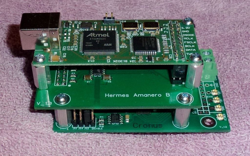
Attach header pins as shown in pic 4 for the stack.
There are alignment dots on the Hermes/Cronus board by the headers.
Attach power connecter VD and ground. Power with 5 volts. The Amanero is powered via USB cable.
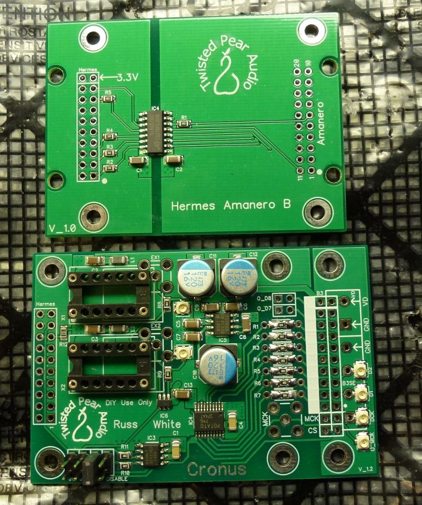
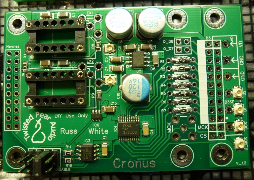
Most of the difficult stuff is mounted. You can use either the included SMD or included through hole resistors in R1 through R7. No advantage to either, whatever you are most comfortable soldering.
Solder the two clock sockets in.
Solder an eight pin header in for the divider jumper.
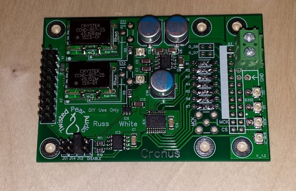
The slower clock goes in the X1 position. There is a dot on Rhea boards that matches dot on Cronus board. (At the Hermes header end).
J 1:2 was the suggested jumper/divider setting for BIII with 45.1584/49.152MHz Rhea Pair.
Match/connect via u.fl cables D1, D2 and DCK from Cronus to same on BIIISE. If running in sync mode, remove shunt module for clock on BIIISE and connect MCK from Cronus to BIIISE EXT_MCK.
Optional: Attach a two pin header on the correct P3 terminals of the Amanero to make flashing easier. The correct terminals are shown in the Amanero readme file with the config tool.
Did you get the Amanero from TP? If so it will be flashed correctly. If not, download the flash tool from Amanero linked off the page below. Check out the readme for correct procedure (when to jumper, when to disconnect, flash, reconnect etc.)
http://amanero.com/combo384_firmware.htmAmanero flash:
CPLD Firmware = set to "Slave_For_1080"
CPU Firmware = "firmware_1096c" or "firmware_1095b" - but do not use "firmware_1095c" as it is broken.
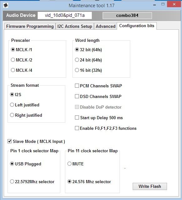
Set config bits per image. If you play DSD files, fairly sure you have to enable DSD channel swap.
EDIT: If you use header pins instead of u.fl, just follow the traces from u.fl connectors to B3 header outline. MCK would be clock, the white dot is DCK, next hole D1, next hole D2. Ground would be the inner row. Hot would be row closest to edge of board.
If you use ribbon cable, best to have ground wire on each side of hot.
Edited by user Monday, January 4, 2016 1:32:39 AM(UTC)
| Reason: Not specified

