Rank: Member
Groups: Member
Joined: 2/2/2010(UTC)
Posts: 20
Location: los angeles
|
Hey All, I've been sitting on a pair of BIII boards for like 4 years and just got around to the build, so very sorry if this seems like a dumb question. If I wanted to connect an I2S source (the USB receiver) to the BIII's directly, what would be a good connector to go in the pins (where the ribbon cable normally goes)? It looks like I'll need 4 per BIII. I suppose I could use the ribbon connector and just splice out the 4 wires needed, but would prefer something cleaner. kinda like this: https://hifiduino.files..../2012/08/fifoandbiii.jpgI'll also need the connector that goes between both BIIIs. I see pictures with this small ribbon cable, but don't seem to have it. I don't seem to have the pins that go on the board or the small ribbon cable/connectors. I got a sidecar as well, but probably won't use it....but I did notice that some folks had both ribbon (in dual mono setup) cables connected to it, and I must be dumb, but don't see how this is done? Is it ribbon cables stacked and then use one connector is pressed through both? http://s835.photobucket....23C_zpshcphvnn4.jpg.html
|
|
|
|
|
|
Rank: Member
Groups: Member
Joined: 2/2/2010(UTC)
Posts: 20
Location: los angeles
|
I think I figured out what needs to be done. Brian sorted me out with all the needed connectors. thanks!
|
|
|
|
|
|
Rank: Member
Groups: Member
Joined: 1/6/2012(UTC)
Posts: 305
Location: Plainfield, IL
Thanks: 11 times
Was thanked: 26 time(s) in 21 post(s)
|
Greetings yammy, Here is how I did it. Depending on jumper use under board, you don't need to connect every terminal. The DAC board normally powers the Sidecar or 4 channel SPDIF input board so you'd need a full width ribbon for that. The Intergartion manual shows pin out for DAC board. It shows which are B+ voltage and ground. I power my Sidecar/4 channel SPDIF input board with separate power supply so I only need inputs. 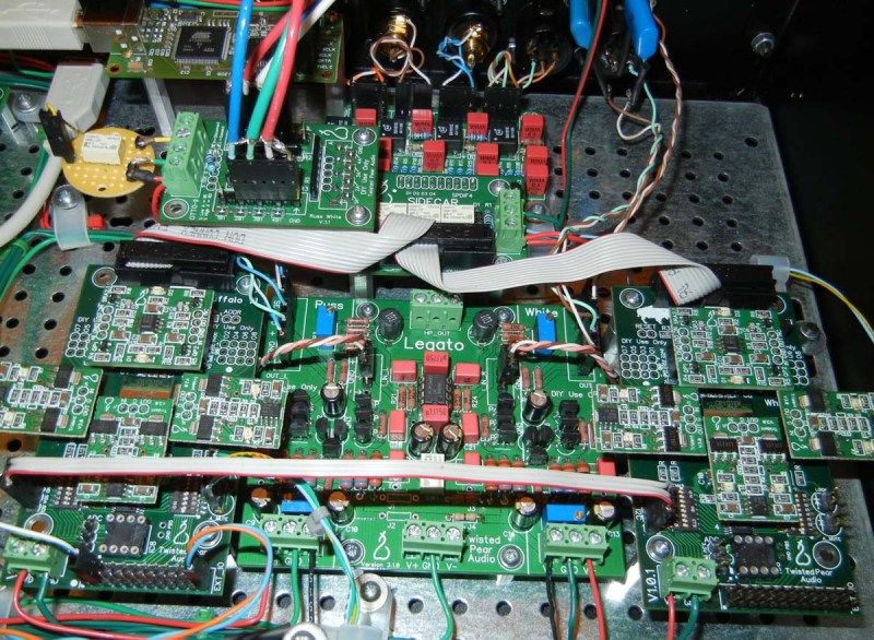 Here is my photobucket dual mono build pic link showing my way. http://s417.photobucket....0Build?sort=6&page=1Also, if you are going to play DSD files, the dual mono configuration will play in mono. Russ has an OTTO II fix for that posted here. I used signal relays to remap DSD instead. |
|
|
|
|
|
|
Rank: Member
Groups: Member
Joined: 2/2/2010(UTC)
Posts: 20
Location: los angeles
|
Hey Everybody, I made a bunch of progress and am at the point where everything is hooked up and lights up right when powered, but can't seem to get a lock in dual-mono configuration. I'm currently running the 'secondary' B3 in stereo mode and that works ok. Lock lights right up and I get sound. If I have everything hooked up as in the picture, the lock never lights up on either DAC. After 10 seconds or so, the MUTE light does go off on the 'primary' DAC and stays on on the secondary (no rom and shorted . I've checked over all the settings and jumpers from the integration guide numerous times and everything looks right. If I disconnect the i2s cables from the primary DAC, the secondary one works as is (addr shorted, R7 shorted, no firmware chip). I've yet to be able to get any lock on the primary DAC, I don't know if it's because it's set up to be the dual-mono 'master' or something else? Any guidance as to what to check next would be of great help! http://imgur.com/Bku5zt7http://imgur.com/4eQhYWQEdited by user Tuesday, September 29, 2015 12:48:30 AM(UTC)
| Reason: Not specified
|
|
|
|
|
|
Rank: Administration
Groups: Administration, Customer
Joined: 10/24/2006(UTC)
Posts: 2,869
Location: Massachusetts, USA
Thanks: 2 times
Was thanked: 141 time(s) in 134 post(s)
|
Please remove the R7 short, as it is not needed.
It is an error in the Integration Guide. It's purpose it to change the I2C address of the port expander.
It likely has nothing to do with the problem you are experiencing, but it might (I would need to test to be sure).
|
|
|
|
|
|
Rank: Member
Groups: Member
Joined: 5/23/2010(UTC)
Posts: 708
Location: Netherlands
Thanks: 2 times
Was thanked: 48 time(s) in 45 post(s)
|
I'm sorry, but that is not an error in the integration guide.
It is specified by Russ in his original Buffalo III DAC Firmware manual (which was never publicly released):
"To keep the port expander on the DAC without the controller from intercepting I2C signals you need to do one of two things on that DAC. Do which ever is easier for you.
1) Remove L5 which completely removes power from that section of the DAC.
2) Jumper R7 (which should arrive empty) which changes the port expander address."
|
|
|
|
|
|
Rank: Member
Groups: Member
Joined: 2/2/2010(UTC)
Posts: 20
Location: los angeles
|
I went ahead and set both up as stereo mode to test each individually. Everything default except the dip switch for SPDIF bypass.
The left board is doing the same thing still. The mute light goes off after about 10 seconds or so, but the lock LED never comes on. All the lights on the board and trident modules look nice and bright.
The right board, I don't know if it was my own doing or what, something that got progressively worse, but it kept losing lock more and more frequently and it's at the point where it's just going on momentarily and then losing lock again.
Plugged the B2 back in using the same IVY and USB-I2S and works fine :)
Any suggestions on what else I should check? Any help is appreciated, thanks!
-Ken
|
|
|
|
|
|
Rank: Administration
Groups: Administration, Customer
Joined: 10/24/2006(UTC)
Posts: 3,979
Location: Nashville, TN
Thanks: 25 times
Was thanked: 89 time(s) in 83 post(s)
|
Time to thoroughly check solder joints etc - do a careful inspection. Check continuity of signals to DAC pins. Check signals if you have a scope.
It is possible that the DAC is damaged (maybe ESD?)
Very sorry.
|
|
|
|
|
|
Rank: Member
Groups: Member
Joined: 2/2/2010(UTC)
Posts: 20
Location: los angeles
|
Thanks for the suggestions. I'll go through and recheck/solder. Any issues removing the SMD jumpers and just doing a solder jumper? Seems a lot easier than handling the tweezer.
I think it's largely on me for letting this sit for so long.
Thanks,
-Ken
|
|
|
|
|
|
Forum Jump
You cannot post new topics in this forum.
You cannot reply to topics in this forum.
You cannot delete your posts in this forum.
You cannot edit your posts in this forum.
You cannot create polls in this forum.
You cannot vote in polls in this forum.

