Rank: Member
Groups: Member
Joined: 6/4/2012(UTC)
Posts: 50
Thanks: 7 times
|
|
|
|
|
|
|
Rank: Member
Groups: Member
Joined: 6/17/2008(UTC) Posts: 921  Thanks: 1 times
Was thanked: 70 time(s) in 69 post(s)
|
First of all. You're supposed to measure across R1 and R2.
Forget the TP_GND1 and TP_GND2 - we don't need those right now.
Measure between TP_VIN+ and TP_CCS+ (mV) - reading:
Measure between TP_SHUNT+ and TP_OUT+ (mV) - reading:
Try turn VR1, can you change the above values ?
|
 1 user thanked avr300 for this useful post.
|
|
|
|
Rank: Member
Groups: Member
Joined: 6/4/2012(UTC)
Posts: 50
Thanks: 7 times
|
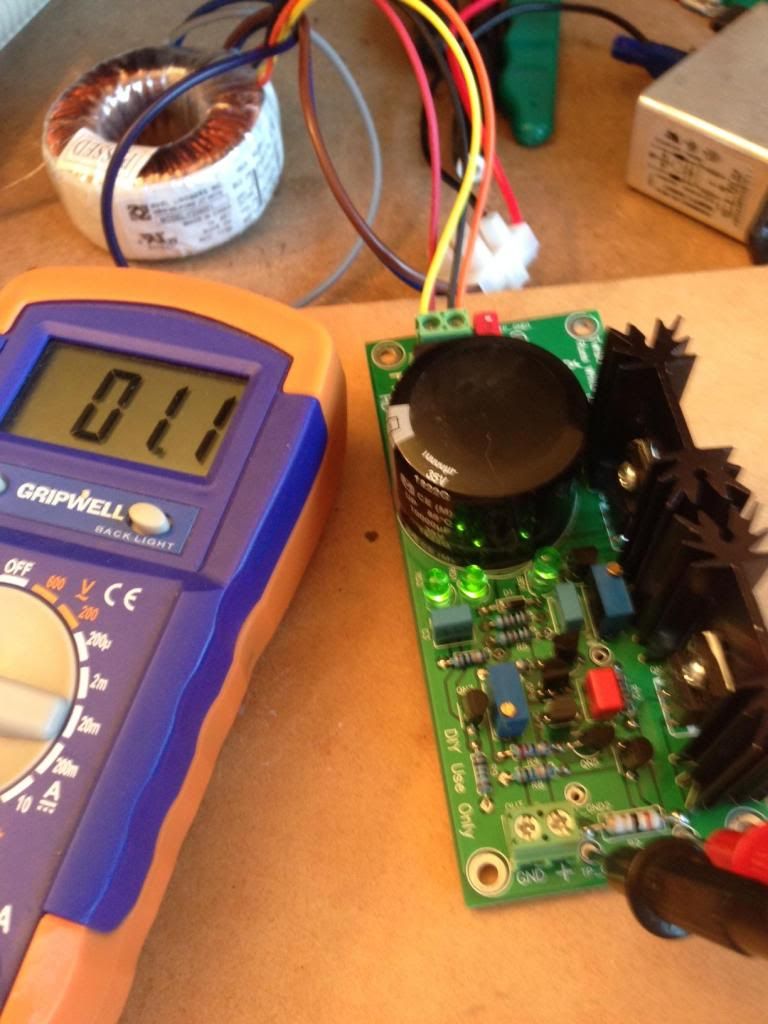
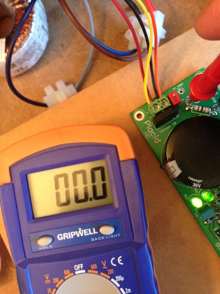
Thanks AVR300 this is what i am getting, as for changing the vr1 no changes happen when i adjust.  
|
|
|
|
|
|
Rank: Member
Groups: Member
Joined: 6/17/2008(UTC) Posts: 921  Thanks: 1 times
Was thanked: 70 time(s) in 69 post(s)
|
Check all the transistors, both small and the big once at heat sinks. Are they all in the correct positions?
|
|
|
|
|
|
Rank: Member
Groups: Member
Joined: 6/4/2012(UTC)
Posts: 50
Thanks: 7 times
|
Sorry avr300 been busy with getting married and stuff. I think the pcb is stuffed, tried originally using lead free silver solder and I was consistently getting frosted looking joints. So I resoldered using leaded solder most look fine (the pics i uploaded are the leaded ones) however some look like the pad has lifted.
So I'm thinking stuff it and get a new set they aren't that expensive.
Will post again in the following weeks.
|
|
|
|
|
|
Rank: Member
Groups: Member
Joined: 6/17/2008(UTC) Posts: 921  Thanks: 1 times
Was thanked: 70 time(s) in 69 post(s)
|
I don't see any pad lifting. To me it looks ok.
Have you double checked all transistor (correct location) ?
Try uploade a good sharp (non-shaken) picture of the component side.
|
|
|
|
|
|
Rank: Member
Groups: Member
Joined: 6/17/2008(UTC) Posts: 921  Thanks: 1 times
Was thanked: 70 time(s) in 69 post(s)
|
And by the way - congrats.
|
|
|
|
|
|
Rank: Member
Groups: Member
Joined: 6/4/2012(UTC)
Posts: 50
Thanks: 7 times
|
|
|
|
|
|
|
Rank: Member
Groups: Member
Joined: 6/17/2008(UTC) Posts: 921  Thanks: 1 times
Was thanked: 70 time(s) in 69 post(s)
|
Those two looks suspicious. Again, pictures of component side (the other side) edit: never mind the first one - that's ground (sorry). Edited by user Sunday, January 19, 2014 10:32:47 AM(UTC)
| Reason: Not specified avr300 attached the following image(s):  cut1.JPG (37kb) downloaded 15 time(s). cut2.JPG (25kb) downloaded 14 time(s).You cannot view/download attachments. Try to login or register.
|
|
|
|
|
|
Rank: Member
Groups: Member
Joined: 6/4/2012(UTC)
Posts: 50
Thanks: 7 times
|
|
|
|
|
|
|
Rank: Member
Groups: Member
Joined: 6/4/2012(UTC)
Posts: 50
Thanks: 7 times
|
Ordered another set, let you know how i go buddy.
|
|
|
|
|
|
Rank: Member
Groups: Member
Joined: 6/17/2008(UTC) Posts: 921  Thanks: 1 times
Was thanked: 70 time(s) in 69 post(s)
|
I don't see anything obvious.
As long as you ensure all transistors are in their correct positions.
|
|
|
|
|
|
Rank: Administration
Groups: Administration, Customer
Joined: 10/24/2006(UTC)
Posts: 2,869
Location: Massachusetts, USA
Thanks: 2 times
Was thanked: 141 time(s) in 134 post(s)
|
With the soldering and resoldering, it's quite possible the trimmers were overheated and killed.
|
|
|
|
|
|
Rank: Member
Groups: Member
Joined: 6/4/2012(UTC)
Posts: 50
Thanks: 7 times
|
Hi Brian
If the trimmers were fried would I still see a change when I turn the dial and measure directly at the trim pot?
|
|
|
|
|
|
Rank: Member
Groups: Member
Joined: 6/4/2012(UTC)
Posts: 50
Thanks: 7 times
|
Originally Posted by: avr300  I don't see anything obvious.
As long as you ensure all transistors are in their correct positions. I couldn't see anything either really, I double checked the qp and qn and they were all correct. I think Brian is right I really tried to get the lead free silver solder to work with multiple resoldering on many parts. As well I had to go to 390+ degrees to get some success. I really did learn a lot through this kit but maybe I was doomed to fail when combining that this was my first go at soldering and I chose a solder that perhaps is not as easy as a normal leaded solder. I remember so many times that I kept resoldering because I kept getting a frosted joint. Then after a while I switched to a leaded solder and the new joints looked fine. So to gain some more experience I did an audiosector lm3875 kit which is now playing on my yamaha ns1000ms beautifully. For such a simple amp it really is keeping up with my weston acoustics kt120. I will get this kit finished even if it kills me. Also what usb to i2s would you recommend? Waveio perhaps?
|
|
|
|
|
|
Rank: Member
Groups: Member
Joined: 6/17/2008(UTC) Posts: 921  Thanks: 1 times
Was thanked: 70 time(s) in 69 post(s)
|
Originally Posted by: feckie  Hi Brian
If the trimmers were fried would I still see a change when I turn the dial and measure directly at the trim pot? No. At least not within the specification of the trimpot (0-20k ohm) With the trimpot in-circuit it is more difficult to measure due to the fact that the whole circuit affect the measured value. But you will still be able to measure a change when trimming. When you get the replacement kit up and running it would be easy to measure and compare the two to find the glitch. usb to i2s - I don't know, I'm using SPDIF only.
|
|
|
|
|
|
Rank: Member
Groups: Member
Joined: 6/4/2012(UTC)
Posts: 50
Thanks: 7 times
|
Originally Posted by: avr300  Originally Posted by: feckie 
When you get the replacement kit up and running it would be easy to measure and compare the two to find the glitch.
i was thinking that as well and if by chance we can fix the glitch whatever it may be then i will have no choice but to upgrade it to mono 
|
|
|
|
|
|
Rank: Member
Groups: Member
Joined: 6/4/2012(UTC)
Posts: 50
Thanks: 7 times
|
Well i have completed the new set and they work like a charm, resoldered the questionable ones and they work fine :).
These spare PSUs will be used for the USB to I2S controller so i dont feel like i lost out much.
I will no doubt create another thread about using a sidecar, S/PDIF 4 and waveio ;)
Thanks for your help guys much appreciated.
|
|
|
|
|
|
Forum Jump
You cannot post new topics in this forum.
You cannot reply to topics in this forum.
You cannot delete your posts in this forum.
You cannot edit your posts in this forum.
You cannot create polls in this forum.
You cannot vote in polls in this forum.