Rank: Member
Groups: Member
Joined: 5/22/2012(UTC) Posts: 21  Location: Guantanamo Bay
|
I have been working on the project for a while for someone else. I have read through any thread I could find concerning dropouts and tried all the fixes mentioned but nothing has fixed it yet. The last thing I did was to check all the solder joints on the dac and its power supply. That seemed to help at first but it has started dropping out again, although not as frequently now.
I also see that most people can run theirs at 5.25V. If I go any higher that 4.85 it will not even try to hold the lock. Right now the Placid is set to 4.8V and it is shunting 50-55mA. QN1's sink gets pretty hot while QN2's is barely warm.
The inputs are coming in through the 4-S/PDIF input board.
When it is working right it sounds great, especially with the Auricap coupling caps. I just need it to work all the time so that it can go to its permanent home. I'm ready to start another project and need this one done.
|
|
|
|
|
|
Rank: Member
Groups: Member
Joined: 5/22/2012(UTC) Posts: 21  Location: Guantanamo Bay
|
Does anyone have any ideas for me? Can the AVCC be causing this? Or could new firmware possibly help? I'm at my wits end trying to fix this thing.
|
|
|
|
|
|
Rank: Administration
Groups: Administration, Customer
Joined: 10/24/2006(UTC)
Posts: 2,869
Location: Massachusetts, USA
Thanks: 2 times
Was thanked: 141 time(s) in 134 post(s)
|
Can you post a picture of your build?
|
|
|
|
|
|
Rank: Member
Groups: Member
Joined: 5/22/2012(UTC) Posts: 21  Location: Guantanamo Bay
|
These are the best I have right now. I will try to get some better close ups of the dac board tonight.  IMG_1439 IMG_1439 by c12mech, on Flickr  IMG_1435 IMG_1435 by c12mech, on Flickr
|
|
|
|
|
|
Rank: Member
Groups: Member
Joined: 6/17/2008(UTC) Posts: 921  Thanks: 1 times
Was thanked: 70 time(s) in 69 post(s)
|
Just curious, are the main caps mounted underneath the Placid boards ? If yes, why ?
|
|
|
|
|
|
Rank: Member
Groups: Member
Joined: 5/22/2012(UTC) Posts: 21  Location: Guantanamo Bay
|
Yes, they are under the boards because they were to tall to fit in the case. I did not use the kit parts for this build at the request of the person I built it for.
To cover my bases, I also tried a stock built power supply and had the same issues. Just wanted to see if it was something there.
|
|
|
|
|
|
Rank: Administration
Groups: Administration, Customer
Joined: 10/24/2006(UTC)
Posts: 3,979
Location: Nashville, TN
Thanks: 25 times
Was thanked: 89 time(s) in 83 post(s)
|
It sometimes helps to connect GND and -IN on the input side of the SPDIF4 for inputs that are consumer level.
Also just double check that the ribbon is conducting very well.
|
|
|
|
|
|
Rank: Administration
Groups: Administration, Customer
Joined: 10/24/2006(UTC)
Posts: 3,979
Location: Nashville, TN
Thanks: 25 times
Was thanked: 89 time(s) in 83 post(s)
|
You might also try a ~47-220uf cap in parallel with C13 on the SPDIF4. You can mount this under the board - just observe polarity.
|
|
|
|
|
|
Rank: Member
Groups: Member
Joined: 5/22/2012(UTC) Posts: 21  Location: Guantanamo Bay
|
Thanks Russ, I will try those things next.
|
|
|
|
|
|
Rank: Member
Groups: Member
Joined: 5/22/2012(UTC) Posts: 21  Location: Guantanamo Bay
|
I tried the couple of things Russ suggested but they did not help. If anything it got worse. Last night I decided to start swapping parts from my own stash one at a time to see what happened. I changed to Placid for the dac board first and all the problems went away except I can still not put more than 4.8v into the dac. I played it for 3 straight hours and it was perfect. I guess now I have to figure out what is going on with the psu. It would also be nice to know why I cannot get it to work at 5.25v. It has not run at that voltage since I built it, as soon as it hits 4.8v or more it will not lock for more than a second or two at most.
|
|
|
|
|
|
Rank: Member
Groups: Member
Joined: 8/17/2010(UTC)
Posts: 368
Location: australia
Thanks: 8 times
Was thanked: 3 time(s) in 3 post(s)
|
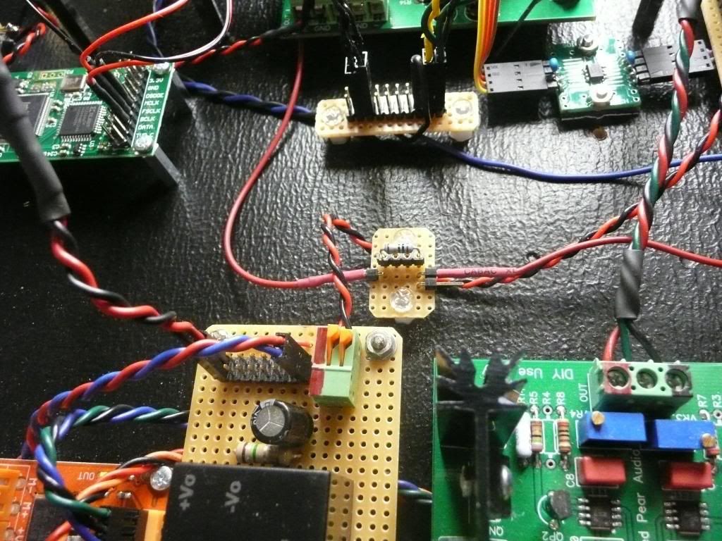
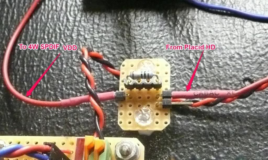
Have you tried lowering the voltage to the 4 Way Spdif? I assume the DAC is feeding the voltage to the 4 Way SPDIF, if it is, then when you lower the voltage to 4.8 volts you are lowering the voltage to the 4 way SPDIF. I would turn the Placid back up to 5.25v, feed the 4 Way Spdif via a resistor to get the volts to 4.8 volts & see how it goes. This is what I did for the resistor, I made it so I could easily change the resistor value, but seem to have hit the right value straight up (10ohms) having said that I still have a lot of testing to do. At the moment there are no dropouts when playing via Toslink or SPDIF.  Edited by user Saturday, June 15, 2013 11:53:24 AM(UTC)
| Reason: Not specified
|
|
|
|
|
|
Rank: Member
Groups: Member
Joined: 5/22/2012(UTC) Posts: 21  Location: Guantanamo Bay
|
Thanks for the info. I went back and read the manual and saw the section about this. Do I cut both vdd wires and add a resistor to both for this to work. I cannot add another psu due to space so I will just be putting a resistor inline with the ribbon cable. What about cutting the trace on the input board and adding the resistor there to keep it out of sight? Just a thought.
|
|
|
|
|
|
Rank: Member
Groups: Member
Joined: 8/17/2010(UTC)
Posts: 368
Location: australia
Thanks: 8 times
Was thanked: 3 time(s) in 3 post(s)
|
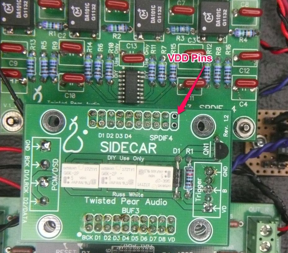
My setup is different, I have stacked my Sidecar, straight on to the 4W SPDIF & the BIII as per the photo. What I did was remove the 2 VDD mating pins of the Sidecar as per the photo. Then I soldered the red wire (other photo, ignore the twisted black & red wire, there just there to confuse things :) ) across both the VDD pins on the 4W SPDIF, on the underside of the board. The red wire run from the 4W SPDIF VDD pins to the resistor cradle & then straight to the Placid +. You can solder the resistor directly to the underside of the 4W SPDIF, once you sure you have the right value resistor. If you solder the resistor directly & you decide to change the value it all gets a bit messy. As I said previously I'm still testing so I cannot 100% confirm the robustness of the change, but it is working fine at the moment.   Edited by user Sunday, June 16, 2013 11:54:48 PM(UTC)
| Reason: Not specified
|
|
|
|
|
|
Rank: Member
Groups: Member
Joined: 5/22/2012(UTC) Posts: 21  Location: Guantanamo Bay
|
I had some extra ribbon cable and made something up by cutting out a section and trying a couple of different size resistors. I have the voltage set to 5.25 and with a 68R in place I get 4.7 going to the input board. It has worked great all night since I did it. I will play it for a few more days while I try to figure out a permanent way to mount things so that it looks good. If it was mine I would leave it like it is but it belongs to someone else. Thanks again for the help with this. Edited by user Monday, June 17, 2013 2:27:17 AM(UTC)
| Reason: I cannot spell!
|
|
|
|
|
|
Rank: Member
Groups: Member
Joined: 5/27/2012(UTC) Posts: 1 
|
 I had the same problem with the S/PDIF-board. Last week I found this topic and try the proposal to add a resistor for VDD. I cut a trace from relais S3.2 pin 4 to VDD pins (19/20) on sidecar and solder a 51 ohm resistor in place. Success! The S/PDIF-voltage at the DAC-inputs is now 3,64Vpp - like the voltage of Amanero USB-converter. Before it was more than 4Vpp. This is too high for a proper function of BIII. I think TP can implement a solution like this for further boards. Rgds Wolfgang Edited by user Wednesday, June 26, 2013 2:10:00 PM(UTC)
| Reason: Not specified koeniwo attached the following image(s):  BII-Sideboard.jpg (83kb) downloaded 19 time(s).You cannot view/download attachments. Try to login or register.
|
|
|
|
|
|
Rank: Member
Groups: Member
Joined: 5/22/2012(UTC) Posts: 21  Location: Guantanamo Bay
|
I'm glad that this topic helped Wolfgang. It took me a while to figure it all out and I cannot thank DQ828 enough for his help. Everything is working perfectly now.
|
|
|
|
|
|
Forum Jump
You cannot post new topics in this forum.
You cannot reply to topics in this forum.
You cannot delete your posts in this forum.
You cannot edit your posts in this forum.
You cannot create polls in this forum.
You cannot vote in polls in this forum.