Rank: Member
Groups: Member
Joined: 8/17/2010(UTC)
Posts: 368
Location: australia
Thanks: 8 times
Was thanked: 3 time(s) in 3 post(s)
|
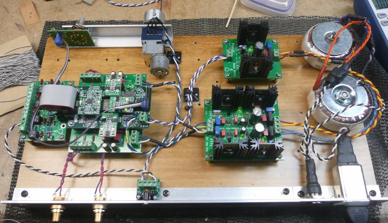
I have just finished putting together my BIII, but I have not been able to get music to play:( Initially I had connected the Toslink Grnd to the Grnd on the 4-Channel S/PDIF (IN A, 10K resistor at R1) & the LOCK light didn't come on, then I realised I should have been connecting the Toslink Grnd to the - at the 4-Channel S/PDIF input, I did this & the MUTE LIGHT went off but LOCK light just flickers & no music plays. I would greatly appreciate any suggestions as my brain if fried :) [img]  [/img]
|
|
|
|
|
|
Rank: Member
Groups: Member
Joined: 5/23/2010(UTC)
Posts: 708
Location: Netherlands
Thanks: 2 times
Was thanked: 48 time(s) in 45 post(s)
|
You might want to try connecting the Toslink module directly to the DAC. Also your (flat)cables are quite long. Rotating the DAC 90 degrees would shorten many signal wires.
|
|
|
|
|
|
Rank: Member
Groups: Member
Joined: 8/17/2010(UTC)
Posts: 368
Location: australia
Thanks: 8 times
Was thanked: 3 time(s) in 3 post(s)
|
Originally Posted by: LeonvB  You might want to try connecting the Toslink module directly to the DAC. Also your (flat)cables are quite long. Rotating the DAC 90 degrees would shorten many signal wires. Leon Thanks, by the way your manual is EXCELLENT, don't know what I would have done without it.
|
|
|
|
|
|
Rank: Member
Groups: Member
Joined: 8/17/2010(UTC)
Posts: 368
Location: australia
Thanks: 8 times
Was thanked: 3 time(s) in 3 post(s)
|
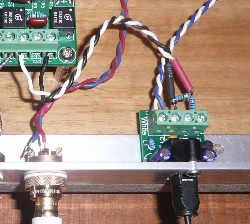
Problem solved, the suggestion (from another thread) of using a voltage divider on the Toslink module output has solved the issue, it appears the Toslink module supplies too large a signal & causes issues with the 4-Channel S/PDIF module, after applying the voltage divider the signal needs to be feed to a 75ohm resistor on the input of the 4-Channel S/PDIF board, i.e., ditch the suggested 10K resistor.
I can't help but think there must be a better way to deal with this issue, but I don't know enough to think of one.
I will also make the changes that LEON suggested as this is just the start for this project.
|
|
|
|
|
|
Rank: Member
Groups: Member
Joined: 8/17/2010(UTC)
Posts: 368
Location: australia
Thanks: 8 times
Was thanked: 3 time(s) in 3 post(s)
|
This is the voltage divider I installed for anyone who is interested. 
|
|
|
|
|
|
Forum Jump
You cannot post new topics in this forum.
You cannot reply to topics in this forum.
You cannot delete your posts in this forum.
You cannot edit your posts in this forum.
You cannot create polls in this forum.
You cannot vote in polls in this forum.