Rank: Member
Groups: Member
Joined: 8/17/2010(UTC)
Posts: 368
Location: australia
Thanks: 8 times
Was thanked: 3 time(s) in 3 post(s)
|
This is too much fun  It's not all beer & skittles though, I spent 3 hrs last night trying to work out why the smaller images wouldn't display, at 11:55 pm I finally worked to that the file names were too long.  It is very hard to take a good photo of the screen I'm not sure how the others manage it. The large lizard displays on start up, then the other images load. When a different source is selected the "Squeezebox" text will change to whatever is selected, there are 4 inputs to choose from. The "Sleep" text changes colour when the sleep function is engaged & the minutes of sleep display display below and count down, although that feature needs some work. The actual volume will display below the "Volume" text & will be incremented from 1 to 99, As yet I haven't implemented the volume part of the display. 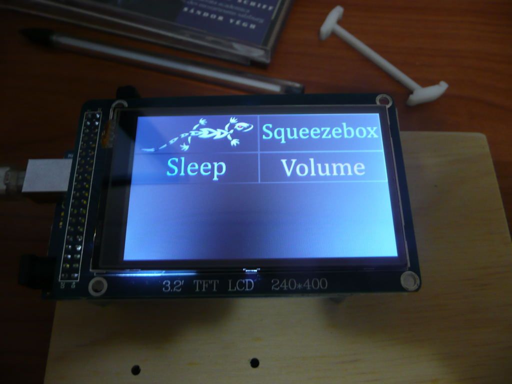 Edited by user Sunday, September 2, 2012 10:39:18 AM(UTC)
| Reason: Not specified
|
|
|
|
|
|
Rank: Member
Groups: Member
Joined: 2/1/2012(UTC)
Posts: 332
Location: The Netherlands
Thanks: 4 times
Was thanked: 18 time(s) in 18 post(s)
|
Looks good. Looks like you seem to manage very well! Is the display mounted onto Arduino Mega? Could you measure for me what the dimensions are with the display mounted to it? Edited by user Sunday, September 2, 2012 3:39:22 PM(UTC)
| Reason: Not specified |
|
|
|
|
|
|
Rank: Member
Groups: Member
Joined: 8/17/2010(UTC)
Posts: 368
Location: australia
Thanks: 8 times
Was thanked: 3 time(s) in 3 post(s)
|
With 15mm standoffs it is 48mm to the top of the screen, the overall length is 112mm. The screen board is 60mm wide. I obviously have the shield in between, which I will leave out when I incorporate it into the final build. The shiel is a bit of a pain because you cannot easily get to the SD card or the other pins. 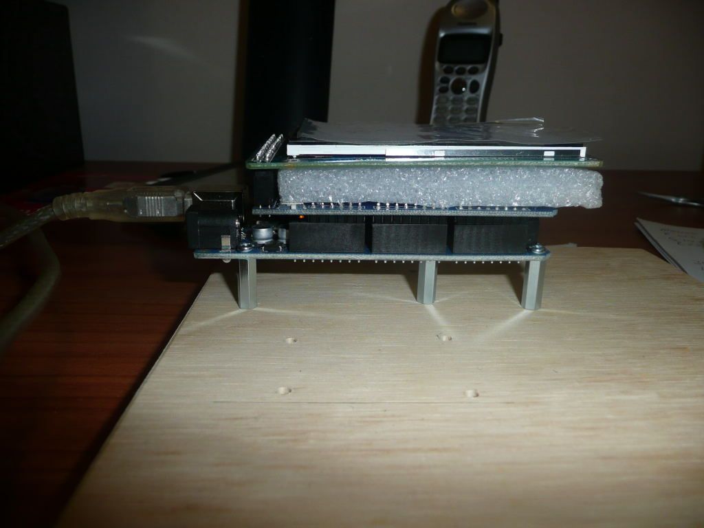
|
|
|
|
|
|
Rank: Member
Groups: Member
Joined: 8/17/2010(UTC)
Posts: 368
Location: australia
Thanks: 8 times
Was thanked: 3 time(s) in 3 post(s)
|
I am getting very close to putting the screen into the system, everything appears to be working as it should. I intend to install it this weekend unless I get bogged down trying to get the Touch screen working, which wasn't part of the original plan. The idea being all of the functions will work from the screen except the "On" function. The plan is to cut the power to the screen once the "Off" has been pressed, to conserve power & screen life. Once I get a handle on the Touch function (assuming I do) I will make some changes to the screen layout to accommodate a "OFF" & Volume Up & Down function. Corpius Thanks for the leg up on the volume code. I have used it in a modified form & the code only reads the volume state when one of the volume buttons are pressed 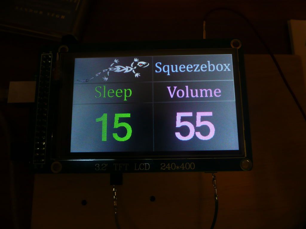 Edited by user Tuesday, September 4, 2012 12:22:05 PM(UTC)
| Reason: Not specified
|
|
|
|
|
|
Rank: Member
Groups: Member
Joined: 8/17/2010(UTC)
Posts: 368
Location: australia
Thanks: 8 times
Was thanked: 3 time(s) in 3 post(s)
|
So much for not getting Bogged Down with the touch function, I think I must have bought the Non Touch version as I cannot get it to respond to save my life. I have made all the changes to the screen graphics in preparation for my break through with the Touch function If I dont have a break through before the weekend I will just install it as is & fix things when I work out what the problem is. 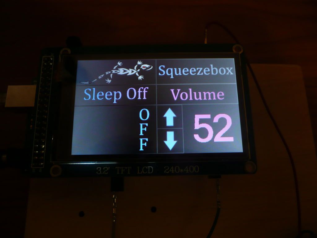 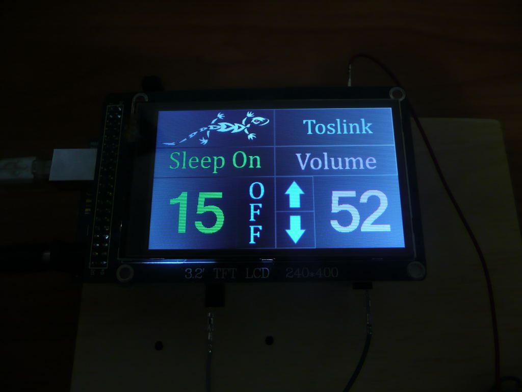
|
|
|
|
|
|
Rank: Member
Groups: Member
Joined: 1/19/2011(UTC)
Posts: 332
Location: Oslo, Norway
Thanks: 14 times
Was thanked: 17 time(s) in 17 post(s)
|
Looks great. I hope you can get the touch function to work also, fingers crossed ;)
|
|
|
|
|
|
Rank: Member
Groups: Member
Joined: 5/22/2012(UTC) Posts: 24  Thanks: 2 times
|
Great Work!!!  Looking forward to your success on the touch function as I have the same screen 
|
|
|
|
|
|
Rank: Member
Groups: Member
Joined: 2/1/2012(UTC)
Posts: 332
Location: The Netherlands
Thanks: 4 times
Was thanked: 18 time(s) in 18 post(s)
|
You're welcome! By looking at your pictures i'm more and more beginning to wonder why I did not go for such a screen.  |
|
|
|
|
|
|
Rank: Member
Groups: Member
Joined: 1/19/2011(UTC)
Posts: 332
Location: Oslo, Norway
Thanks: 14 times
Was thanked: 17 time(s) in 17 post(s)
|
Next step Android control via network shield 
|
|
|
|
|
|
Rank: Member
Groups: Member
Joined: 2/1/2012(UTC)
Posts: 332
Location: The Netherlands
Thanks: 4 times
Was thanked: 18 time(s) in 18 post(s)
|
indeed, but then I definitely need a larger chassis. Perhaps i'll buy one. Luckily I mounted all modules on a separate plate that slides into the chassis. If I'll buy a hifi2000 chassis that has the same width and is a few cm deeper than using the tft screen and combining it with a network shield would become possible. hmmm. tempting.... |
|
|
|
|
|
|
Rank: Member
Groups: Member
Joined: 2/16/2009(UTC)
Posts: 35
Location: netherlands
Thanks: 1 times
|
Looks veeeeeery nice!
Hope you will succeed in getting the touch-thing going!
Keep following you ,
Ed
|
|
|
|
|
|
Rank: Member
Groups: Member
Joined: 8/17/2010(UTC)
Posts: 368
Location: australia
Thanks: 8 times
Was thanked: 3 time(s) in 3 post(s)
|
Thanks for the encouragement, I think I'm going to need help with this one though, I have put a question on the Arduino forum but no response as yet. I have worked out that the out screen does work, so that's a start.
Installing the screens going to get messy, there will be more wires than I care to think about. It would be good if the shield designers would leave access to all of the pins that are not used by the shield.
|
|
|
|
|
|
Rank: Member
Groups: Member
Joined: 8/17/2010(UTC)
Posts: 368
Location: australia
Thanks: 8 times
Was thanked: 3 time(s) in 3 post(s)
|
Originally Posted by: gwikse  Next step Android control via network shield Please excuse the ignorance, what will that do for me?
|
|
|
|
|
|
Rank: Member
Groups: Member
Joined: 8/17/2010(UTC)
Posts: 368
Location: australia
Thanks: 8 times
Was thanked: 3 time(s) in 3 post(s)
|
Does anyone know why they use pins 2 to 6 for the touch screen,? do they need to use the PWM pins? I would like to use pins 42 to 46 just because I am already using the other pins in my setup if I dont have to change everything around that would be good, I'm confused enough as it is  Edited by user Friday, September 7, 2012 9:42:03 AM(UTC)
| Reason: Not specified
|
|
|
|
|
|
Rank: Member
Groups: Member
Joined: 1/19/2011(UTC)
Posts: 332
Location: Oslo, Norway
Thanks: 14 times
Was thanked: 17 time(s) in 17 post(s)
|
Originally Posted by: DQ828 Originally Posted by: gwikse Next step Android control via network shield Please excuse the ignorance, what will that do for me? It will make a connection to the network in your house. IE a wireless router that you also have an android phone/tablet or iphone/ipad connected to. Then if all the stars are aligned we could control the dac from those devices. ;)
|
|
|
|
|
|
Rank: Member
Groups: Member
Joined: 8/17/2010(UTC)
Posts: 368
Location: australia
Thanks: 8 times
Was thanked: 3 time(s) in 3 post(s)
|
If smoke doesn't come out when I turn this lot on I'll be amazed. The pin layout boggles the mind. 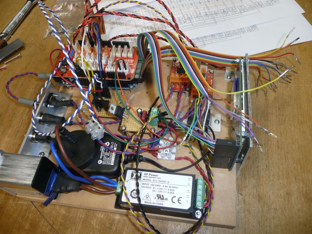 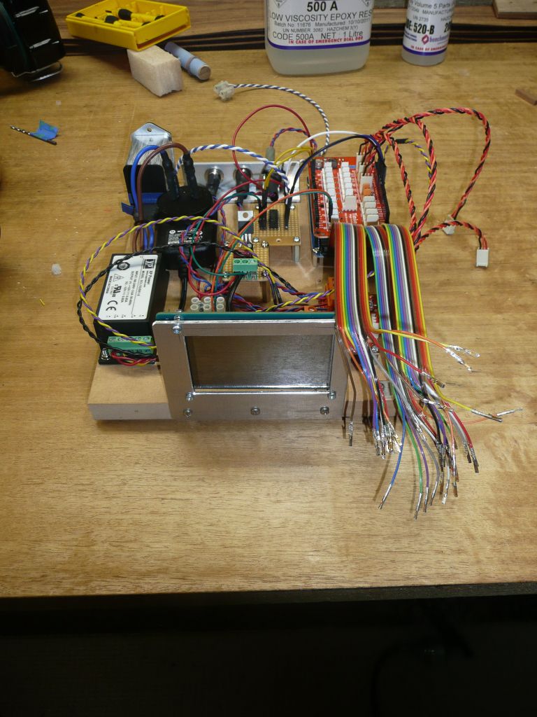 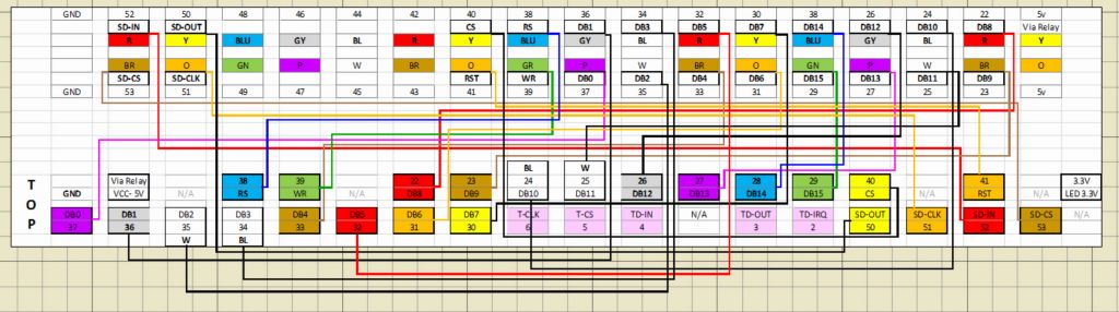
|
|
|
|
|
|
Rank: Member
Groups: Member
Joined: 8/17/2010(UTC)
Posts: 368
Location: australia
Thanks: 8 times
Was thanked: 3 time(s) in 3 post(s)
|
No smoky but no worky Before I waste any more time, is my assumption correct in that all I needed to do, was connect the Arduino pins straight to the screen? I notice the shield has what I think are buffer chips, but I'm not sure exactly what they do. I think I may just bin the last 12hrs of work & rebuild the whole thing using the screen shield. At least the screen still works. Edited by user Saturday, September 8, 2012 5:00:23 AM(UTC)
| Reason: Not specified
|
|
|
|
|
|
Rank: Member
Groups: Member
Joined: 8/17/2010(UTC)
Posts: 368
Location: australia
Thanks: 8 times
Was thanked: 3 time(s) in 3 post(s)
|
It turned out I had the SD card Pin out incorrect, I followed the pinout on Hifiduino, I can only assume the boards pinout has changed as my one is a newer version, obviously I should have followed the data sheet :) BUT all is not well as you can see in the photo. As much as I dont want to rebuild the whole thing I think it is probably for the best. I just hope it's not the other components that are already on the proottype setup that are causing the issue, I'd hate to rebuild the whole thing only to end up with the same problem. 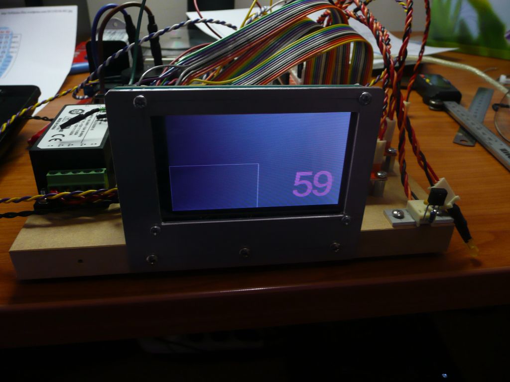 Edited by user Saturday, September 8, 2012 6:46:28 AM(UTC)
| Reason: Not specified
|
|
|
|
|
|
Rank: Member
Groups: Member
Joined: 2/1/2012(UTC)
Posts: 332
Location: The Netherlands
Thanks: 4 times
Was thanked: 18 time(s) in 18 post(s)
|
why don't you a make lengthening to the connecting between the tft shield and Arduino? If the lengthening is long enough it should allow you to use the shield while still maintaining access to the other pins. |
|
|
|
|
|
|
Rank: Member
Groups: Member
Joined: 8/17/2010(UTC)
Posts: 368
Location: australia
Thanks: 8 times
Was thanked: 3 time(s) in 3 post(s)
|
Corpius I was already committed (some say should be committed :) ) to the design you see below. I'm glad to say it all appears to work fine, I haven't tested all of the functions as yet as I have not installed it into the system. Tonight I'm going to have another go at the touch screen (with a little help from a friend) before I install it into the system. As you will see I have soldered header pins to the back of the Mega for easy access. I have put condons on the pins I not using :) 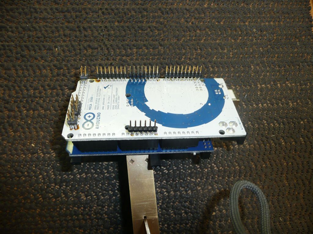 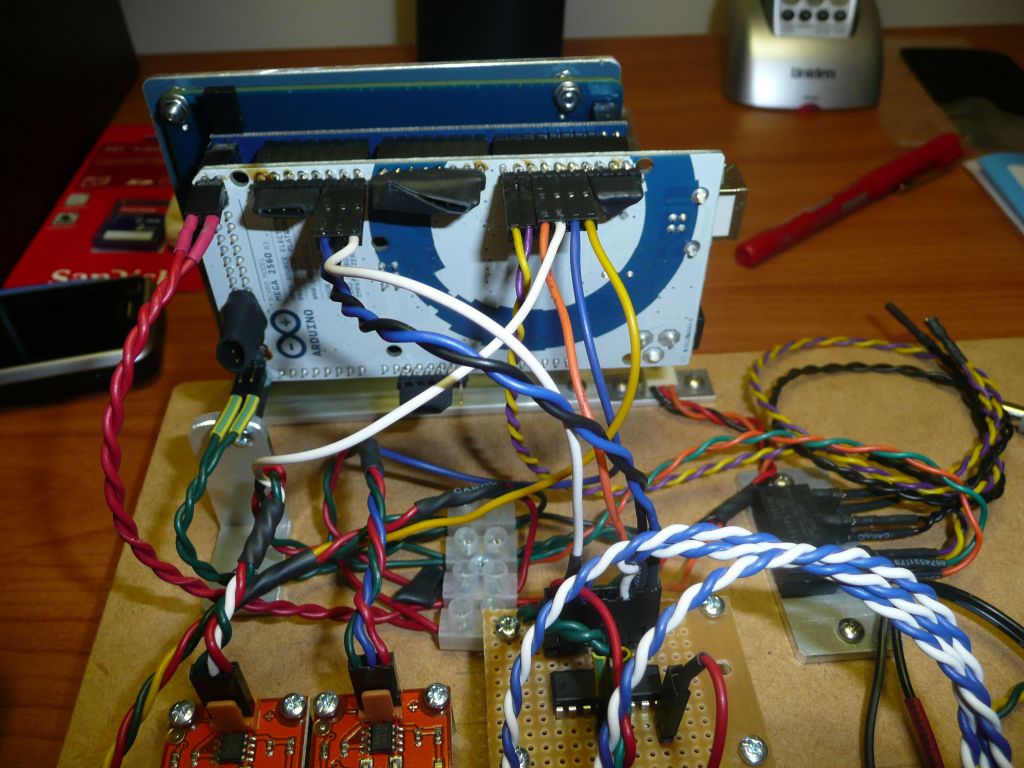 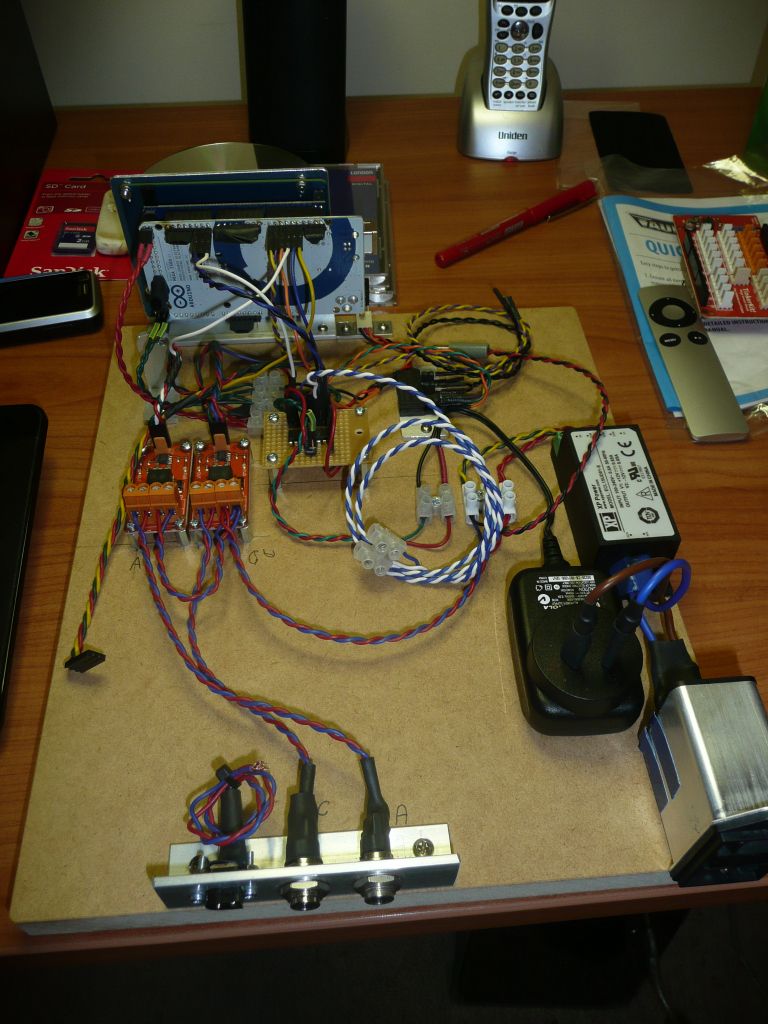 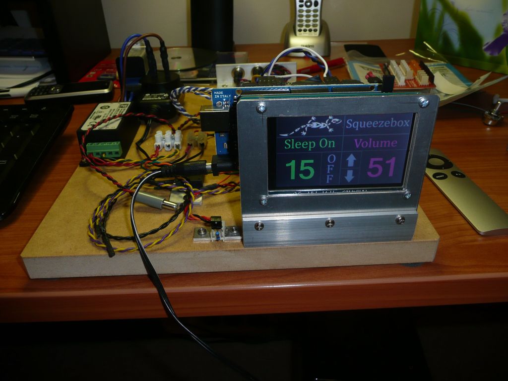 Edited by user Sunday, September 9, 2012 7:19:32 AM(UTC)
| Reason: Not specified
|
|
|
|
|
|
Forum Jump
You cannot post new topics in this forum.
You cannot reply to topics in this forum.
You cannot delete your posts in this forum.
You cannot edit your posts in this forum.
You cannot create polls in this forum.
You cannot vote in polls in this forum.

