Rank: Member
Groups: Member
Joined: 1/6/2012(UTC)
Posts: 305
Location: Plainfield, IL
Thanks: 11 times
Was thanked: 26 time(s) in 21 post(s)
|
Wow, that is a huge screen! You could watch movies on it. ;) Are the code changes difficult to make the large display work? Nice work! Edited by user Sunday, September 9, 2012 6:29:18 PM(UTC)
| Reason: Not specified |
|
|
|
|
|
|
Rank: Member
Groups: Member
Joined: 8/17/2010(UTC)
Posts: 368
Location: australia
Thanks: 8 times
Was thanked: 3 time(s) in 3 post(s)
|
Originally Posted by: SCompRacer  Wow, that is a huge screen! You could watch movies on it. ;)
Are the code changes difficult to make the large display work? Nice work! They come bigger, I was just wondering yesterday how I could get the football on it :) If you use libraries from this site & the associated screens I would say no it's not hard although I am code challenged so if I stray from the norm I get lost easily. Edited by user Monday, September 10, 2012 12:21:55 AM(UTC)
| Reason: Not specified
|
|
|
|
|
|
Rank: Member
Groups: Member
Joined: 5/22/2012(UTC) Posts: 24  Thanks: 2 times
|
Are you using the shield from iTeadstudio? I can't access the SD using the Megasheild.
|
|
|
|
|
|
Rank: Member
Groups: Member
Joined: 8/17/2010(UTC)
Posts: 368
Location: australia
Thanks: 8 times
Was thanked: 3 time(s) in 3 post(s)
|
Yes I'm using the shield from itead, it's a stupid design, I was have to pull the thing apart to get to the SD Card. I'd happily pay lots more for a good shield that gave access to all of the pins & the SD card etc. The Tinkerkit shield is pretty good but not with the screen. Unfortunately it's not all smooth sailing on my end, the screen on it's own works fine, the rest of the system on it's own works fine but when I put the two together the Remote is very erratic, also when I turn power on one of the relay switches on and off twice, it's getting a be frustrating. Oh, I don't even want to talk about the touch controls  There seems to be a conflict between the remote & the touch function. Edited by user Monday, September 10, 2012 11:11:37 PM(UTC)
| Reason: Not specified
|
|
|
|
|
|
Rank: Member
Groups: Member
Joined: 5/22/2012(UTC) Posts: 24 Thanks: 2 times
|
HiFiduino just posted a link using the iTeadstudio touch screen and arduino, very good example for touch control!!
|
|
|
|
|
|
Rank: Member
Groups: Member
Joined: 8/17/2010(UTC)
Posts: 368
Location: australia
Thanks: 8 times
Was thanked: 3 time(s) in 3 post(s)
|
Originally Posted by: bigpanda HiFiduino just posted a link using the iTeadstudio touch screen and arduino, very good example for touch control!! Thanks I'm on it :)
|
|
|
|
|
|
Rank: Member
Groups: Member
Joined: 8/17/2010(UTC)
Posts: 368
Location: australia
Thanks: 8 times
Was thanked: 3 time(s) in 3 post(s)
|
I'm very glad to report I seem to have overcome my relay & remote issues with the new install , I found a problem in my code that appears to have been causing the issues  Haven't done extended testing yet to confirm, seems all good though. I need to make an adjustment to the code re the volume read as it is reading the volume it WAS on not the volume it IS on. With the Touch function it is still a work in progress, I'm starting to wonder if the UTFT & Touch libraries have issues, all the example code I have seen using the Touch is using the older Graph16 library. 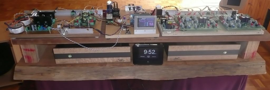
|
|
|
|
|
|
Rank: Member
Groups: Member
Joined: 1/19/2011(UTC)
Posts: 332
Location: Oslo, Norway
Thanks: 14 times
Was thanked: 17 time(s) in 17 post(s)
|
|
|
|
|
|
|
Rank: Member
Groups: Member
Joined: 8/17/2010(UTC)
Posts: 368
Location: australia
Thanks: 8 times
Was thanked: 3 time(s) in 3 post(s)
|
It's impossible to keep up :)
|
|
|
|
|
|
Rank: Member
Groups: Member
Joined: 1/6/2012(UTC)
Posts: 305
Location: Plainfield, IL
Thanks: 11 times
Was thanked: 26 time(s) in 21 post(s)
|
Your bravery has got me hooked so I have an Arduino Uno, rotary encoder and 4x20 display on the way. I'm starting small.....and will need lots of help.  Could I just use one half of my LCDPS to power it? IIRC someone told me I can power the board direct and not go through the AC adapter power input? Edited by user Wednesday, September 12, 2012 5:32:11 PM(UTC)
| Reason: Not specified |
|
|
|
|
|
|
Rank: Member
Groups: Member
Joined: 2/1/2012(UTC)
Posts: 332
Location: The Netherlands
Thanks: 4 times
Was thanked: 18 time(s) in 18 post(s)
|
The Uno can be powered through the usb input, but than you`ll need to connect it to a computer or a usb psb. If I where you I`d power it by using the other power input by using a 7 to 12 volt dc power supply. If you have the LCDPS set for 7 to 12 volt, then it should be no problem to use it. The uno takes maximal 500 mA if I remember well.. So make sure the ps has enough left. |
|
|
|
|
|
|
Rank: Member
Groups: Member
Joined: 8/17/2010(UTC)
Posts: 368
Location: australia
Thanks: 8 times
Was thanked: 3 time(s) in 3 post(s)
|
Originally Posted by: SCompRacer Your bravery has got me hooked so I have an Arduino Uno, rotary encoder and 4x20 display on the way. I'm starting small.....and will need lots of help. Could I just use one half of my LCDPS to power it? IIRC someone told me I can power the board direct and not go through the AC adapter power input? It sounds like you are going to follow the Hifiduino implementation which I would have to recommend even though I haven't done it myself, if you followed mine it would be the blind leading the blind :)
|
|
|
|
|
|
Rank: Member
Groups: Member
Joined: 8/17/2010(UTC)
Posts: 368
Location: australia
Thanks: 8 times
Was thanked: 3 time(s) in 3 post(s)
|
Corpius
I have implemented the volume control as per your advice using the ALPS 10k motorised linear pot you see in the photo's, there is an issue with the actual volume readings displayed at high and and low levels, I get weird readings, once below 30 & above 70 (approx). I would have assumed a linear pot would give me a consistent change.
Any thought's on what might be causing the problem?
|
|
|
|
|
|
Rank: Member
Groups: Member
Joined: 2/1/2012(UTC)
Posts: 332
Location: The Netherlands
Thanks: 4 times
Was thanked: 18 time(s) in 18 post(s)
|
1. What exactly do you mean with weird readings? 2. Try to find out what the original AnalogRead readings are for the whole range. You can show them on the display instead of the calculated value, just comment the calculation step after the analogRead. The readings should be linear and go up and down from 0 to 1023. 3. Are you absolutely sure it is an linear pot you're using? 4. Could you post the exact code you are using? Edited by user Thursday, September 13, 2012 6:06:50 PM(UTC)
| Reason: I was wrong about the calculation part, so I removed it :-) |
|
|
|
|
|
|
Rank: Member
Groups: Member
Joined: 8/17/2010(UTC)
Posts: 368
Location: australia
Thanks: 8 times
Was thanked: 3 time(s) in 3 post(s)
|
Originally Posted by: Corpius 1. What exactly do you mean with weird readings?
2. Try to find out what the original AnalogRead readings are for the whole range. You can show them on the display instead of the calculated value, just comment the calculation step after the analogRead. The readings should be linear and go up and down from 0 to 1023.
3. Are you absolutely sure it is an linear pot you're using?
4. Could you post the exact code you are using? 1. At the low volume end, weird like jumping from 15 to 96!! as the next progression, at the high volume end, hardly changing at all. 2. Will do. 3. I have tested the pot & it is linear although it only appears to go from 10k to 1.8k, at the 50% mark it reads about 5k 4. #define potPin A0 // define the analog pin, pin A0 in this case //Code In Void Setup void DisplayVolume() // display the volume { int val = 0; // variable to store the value coming from the potentiometer int volumeToDisplay; // variable to store the volume to be displayed val = analogRead(potPin); // read the value from the sensor volumeToDisplay = (val / 11); // calculate the volume Serial.println(volumeToDisplay); myGLCD.setFont(Shruti_Bold_num_48x70); myGLCD.setColor(153, 0, 255); myGLCD.printNumI(volumeToDisplay, 285, 146); Then” DisplayVolume()” is used throughout the code to display the volume as required
|
|
|
|
|
|
Rank: Member
Groups: Member
Joined: 2/1/2012(UTC)
Posts: 332
Location: The Netherlands
Thanks: 4 times
Was thanked: 18 time(s) in 18 post(s)
|
According to you findings I`d say you do not have a linear pot and connected it in reverse. See graph:  Connecting it in reverse doesn`t matter for displaying the correct volume value. Adjust the calculation, just subtract the calculated value from the maximum displayed value. But first try to read the analogRead values. Edited by user Friday, September 14, 2012 9:32:29 AM(UTC)
| Reason: Not specified |
|
|
|
|
|
|
Rank: Member
Groups: Member
Joined: 8/17/2010(UTC)
Posts: 368
Location: australia
Thanks: 8 times
Was thanked: 3 time(s) in 3 post(s)
|
Originally Posted by: Corpius According to you findings I`d say you do not have a linear pot and connected it in reverse. See graph: Connecting it in reverse doesn`t matter for displaying the correct volume value. Adjust the calculation, just subtract the calculated value from the maximum displayed value. But first try to read the analogRead values. Iv'e got bigger problems than that :) I changed the display to show the values between 0 & 1023 at one stage I had a value of 7772 displaying :) Holy mackerel Batman!!
|
|
|
|
|
|
Rank: Member
Groups: Member
Joined: 2/1/2012(UTC)
Posts: 332
Location: The Netherlands
Thanks: 4 times
Was thanked: 18 time(s) in 18 post(s)
|
Now that's odd! This shouldn't be possible. Are you sure you are displaying the analogRead value's? http://arduino.cc/en/Reference/analogReadOne other thing. By looking at your code you should subtract the calculated value from the maximum displayed value, otherwise the displayed values will go down when you set the volume up. :-) |
|
|
|
|
|
|
Rank: Member
Groups: Member
Joined: 8/17/2010(UTC)
Posts: 368
Location: australia
Thanks: 8 times
Was thanked: 3 time(s) in 3 post(s)
|
I an sure I am reading/displaying the analogRead values, if you turn the pot slowly the values end up at 1023.
I am thinking maybe I have a PSU/grounding issue that is causing a few minor problems. I am using a Nokia charger to get 5v to the pot motor, while the motor driver IC is driven from the Mega, there is a separate 12v supply for the Mega which drives everything else.
I have noticed the unit does some weird things if you get the grounding wrong, my mistakes have shown that. :)
I am going to get a single supply that will give me both 12v & 5v and see how things go.
The volume display doesn't go down when it's turned up?
|
|
|
|
|
|
Rank: Member
Groups: Member
Joined: 2/1/2012(UTC)
Posts: 332
Location: The Netherlands
Thanks: 4 times
Was thanked: 18 time(s) in 18 post(s)
|
Originally Posted by: DQ828 I am going to get a single supply that will give me both 12v & 5v and see how things go Why don't you use the 5V from Arduino to power the motorpot? Originally Posted by: DQ828 The volume display doesn't go down when it's turned up? Sorry you are right, I must have had a brain fart.  Edited by user Saturday, September 15, 2012 8:59:36 AM(UTC)
| Reason: Not specified |
|
|
|
|
|
|
Forum Jump
You cannot post new topics in this forum.
You cannot reply to topics in this forum.
You cannot delete your posts in this forum.
You cannot edit your posts in this forum.
You cannot create polls in this forum.
You cannot vote in polls in this forum.

